Microprogrammed Control for Efficient Computing Systems
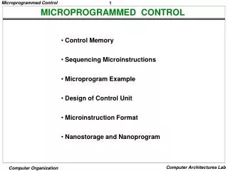
Microprogrammed control involves storing binary control values as words in memory, known as microinstructions, to execute microoperations. The control unit reads microprograms from ROMs to execute actions within the data path and control unit. This method allows for flexible sequencing and activation of microoperations efficiently. Learn about the structure, components, and benefits of microprogrammed control in computer architecture.

Microprogrammed Control for Efficient Computing Systems
E N D
Presentation Transcript
MicroProgrammed Control Chapter 8 (Mano & Kime)
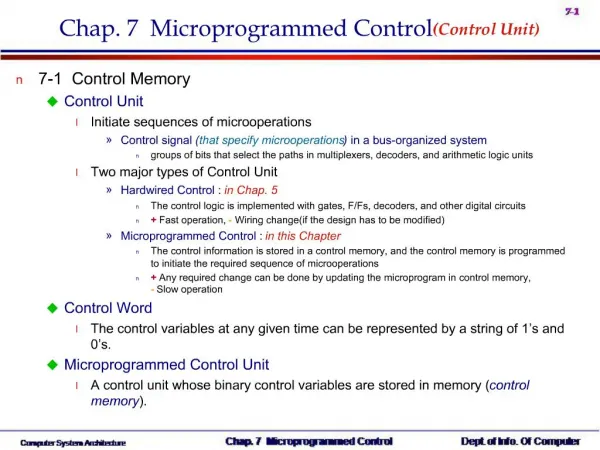
Microprogrammed Control • A control with its binary control values stored as words in memory is called a microprogrammed control. • Each word is a microinstruction that contains one or more microoperations. • A sequence of microinstructions constitute a microprogram.
Microprogrammed Control • Microprograms are stored in ROMs. • The content of a word at a given address specify the microoperations to be performed for both the data path and the control unit. • The memory in the control unit is called control memory (ROM) or writable control memory (RAM).
Microprogrammed Control • The microinstruction contains bits for activating microoperations in the data path and the sequence of microinstructions executed. • The next address maybe • Next • External address • Another address in memory(may be coditional) • The next address generator in combination with CAR is sometimes called a microprogram sequencer.
Microprogrammed Control • The CDR holds the present microinstruction while the next address is being computed and the next microinstruction being read from the memory. • Inserting a CDR is like inserting a pipeline platform (increase performance) • Inclusion of a CDR however, complicates sequencing especially when status bits are involved in decision making. • For simplicity we omit CDR and take control signals directly from the ROM outputs.
Microprogrammed Control • The output signals remain on the outputs as long as the address is applied. • So at each clock signal a microinstruction is executed and a new address is transferred to CAR. • Status bits are only affective on the determination of the next address. This results in moore-type sequential circuits for control design. • ASM charts are not allowed to contain conditional outputs. This means more states.
Binary Multiplier Example Three things to determine are: • Bits in the control word for microinstructions • The sizes of the ROM and the CAR • The structure of the next address generator.
Binary Multiplier • Four control signals are needed for the data path to perform multiplication.
Binary Multiplier The remainder of the microinstruction control word is devoted to the sequencing. NXTADD0 is taken if status not satisfied NXTADD1 is taken if status satisfied
Binary Multiplier Word length is 12 5 states – 5 words
A Simple Computer Architecture • The operations to be performed by the computer are instructed by the user. • A sequence of instructions is called a program. • An instruction is a collection of bits that instructs the computer to perform a specific operation. • The operation code, “opcode”, of an instruction is a group of bits that specifies an operation. • The collection of instructions for a computer is called an instruction set and through description of the instruction set its instruction set architecture.
A Simple Computer Architecture • The control unit fetches an instruction from memory, decodes the opcode and generates necessary control and timing signals. • For 2m distinct operations opcode must be assigned m bits. • An instruction consits of op-code an address fields for the operands. • Address may be • explicit or • implicit.
Instruction Formats • For an 8 register computer the following formats can be assumed. Register addressing: The three operands are the sources (A and B) and the destination. The operation is performed on the contents of the surce registers and the result is stored in the destination register.
Instruction Formats • Immediate addressing • One of the operands is a constant in the instruction (OP field). • The operation is performed on OP and the content of register A and the result is stored in DR.
Instruction Formats • PC Relative addressing • Next instruction to be executed is traced by a special register called program counter, PC. • Execution sequence of instructions can be altered depending on the result of an operation. • Jump and branch instructions are used for this purpose • Jump can be unconditional or conditional. • Next address is calculated by adding the 6-bit offset in the instruction to the content of PC. • Offset may be positive or negative value represented in 2’s complement form.
Instruction Formats • Suppose that we have a memory with 16 bits per word and the opcodes contain 7 bits. [R4] = 70, [R5]=80
Instruction Formats • An operation is specified by an instruction stored in memory. • Control unit fetches the instruction addressed by the PC and decodes it to perform required microoperations to execute the instruction. • Microoperation is specified by the bits in a control word produced by hardware or read from control memory. • The control word is decoded by the computer hardware to execute the microoperation.
Single Cycle Hardwired Control Block Diagram for a Single-Cycle Computer
Bits 11 through 9 select condition for branch (BC) 000 C 001 N 010 V 011 Z 100 C 101 N 110 V 111 Z Instruction Decoder The instructional decoder is a combinational circuit that provides all the control words for the datapath, based on the contents of the fields of the instruction. Bit 13 = 1 jump Bit 13 = 0 conditional branch
Instruction Decoder PL is for loading of PC. For PL=0 PC is incremented If PL=1, JB=1 jump If PL=1, JB=0 conditional branch Bits 13, 14, 15 provide the logic for 1-bit control (MD,RW, MW, PL, JB). Last 5 bits of op-code is for FS
Sample Instructions and Program ADI DR, SA, I R[DR] R[SA] +zf I(2:0) MB MD RW MW PL JB Op-code 1000010 1 0 1 0 0 X MB is 1 constant is selected for B bus Op-code 1000010 FS for add (A (source reg) + B (zerofilled const.) MD is 0 function unit output is selected for D bus RW is 1 D bus is written into DR register MW is 0 no write into memory At the beginning of next cycle DR is written and PC is incremented.
Sample Program Assume that R3 contains 248, location 248 in memory contains 2, location 249 in memory contains 83 the result is to be placed in memory location 250 program that accomplishes the arithmetic expression 83 – (2 + 3) is as follows:
Sample Program LD R1, R3 load R1 with M[R3] (R1 = 2) ADI R1, R1, 3 add 3 to R1 (R1 =5) NOT R1, R1 complement R1 INC R1, R1 increment R1 (R1 = -5) INC R3, R3 increment R3 (R3 = 249) LD R2, R3 load R2 with M[R3] (R2 = 83) ADD R2, R2, R1 R2 [R2] + [R1] (R2 = 78) INC R3, R3 increment R3 (R3 = 250) ST R3, R2 store R2 in M[R3] (memory location 250) M[250] = 78
Path Delay in a Single Cycle Computer Single cycle computer has a lower limit on the clock period, based on a long worst case delay path. Instruction execution takes 17ns 58.8 Mhz clock speed is required.
Single Cycle Computer • Implementation of complex instructions is not possible • If there is only one memory for both instructions and data, at least two access to memory is needed for fetching the instruction and the operand.
Let us add LRI – Load Register Indirect instruction which loads a register with the memory content indirectly addressed by the register. R[DR] M[M[R[SA]]] We need 4 clock cycles. To perform this operation without LRI instruction needs two LD operations which results in 6 cycles
The Hardwired Alternative Block diagram of Hardwired Counter and decoder based Computer
CR = EX0.LRI + EX1 RW = EX0.ST + EX1 The Hardwired Alternative • Derivation of control signals: • CR: The synchronous counter reset To return to state IF Counter is reset (CR=1) • RW: The register file is written in state EX0 for instructions ADI, LD, INC, NOT, ADD, and LRI. In EX1, the register file is also written.
Pipelined Control Suppose we need to load registers 1-7 with numbers 1-7.The program to do this is as follows: 1 LDI R1, 1 2 LDI R2, 2 3 LDI R3, 3 4 LDI R4, 4 5 LDI R5, 5 6 LDI R6, 6 7 LDI R7, 7
Pipelined Control • If we assume that we need at least 5ns (clock cycle200 MHz) for each stage this means that a single instruction executes in 20 ns. • We have 1 + ¾ + ½ + ¼ = 2.5 instructions in 4 clock periods. • The completion of 7-instruction program requires 10 cycles, 50 ns compared to 119 ns (17ns x 7) for single cycle computer, and the program is executed 2.4 times faster.
Pipelined Control • In the first three stages, the pipeline is filling, not all stages are active. • In the last three stages, the pipeline is emptying, not all stages are active. • In 20ns • pipelined computer executes 4 instructions • Single cycle computer executes 20/17 = 1.18 instructions. • The pipelined computer is 4/1.18 = 3.4 times faster