Download
1 / 82
820 likes | 1.1k Views
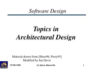
VCC: Function-Architecture Co-Design: Modelling and Examples EE 249: November 7, 2002. Grant Martin Fellow, Cadence Berkeley Labs With thanks to Frank Schirrmeister, Jean-Yves Brunel and Paolo Giusto. Agenda. System-level SoC Design – The Rise in Abstraction

E N D
VCC: Function-Architecture Co-Design: Modelling and ExamplesEE 249: November 7, 2002 Grant Martin Fellow, Cadence Berkeley Labs With thanks to Frank Schirrmeister, Jean-Yves Brunel and Paolo Giusto
Agenda • System-level SoC Design – The Rise in Abstraction • The VCC Design Flow as an example of Function-Architecture Co-Design • Performance Modeling • Architectural Services • Co-Design Example: Automotive Distributed SW • Co-Design Example: Design Space Exploration of Multimedia platform
SystemEnvironment Zone 4: Global Requirements Specification Satellite Specification Untimed, Unclocked, C/C++ Level Zone 3: Suburban Embedded Systems Design Zone 2: Urban Zone 1: In-Building Pico-Cell Micro-Cell Macro-Cell EmbeddedSoftware RefinementDesign Export P/C µ Testbench Analog Memory SOC Implementation Timed, Clocked, RTL Level Firmware Software CORE Embedded System on Chip (SoC) Design Characterization Implementation
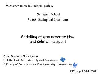
Digital Abstraction Switching delay of the transistor Interconnect delay between transistors 1970’s The design complexity exceeds what designers can comprehend and think through at the layout level Transistor level simulation allows to verify the logic of digital and analog designs based on transistor switching characteristics Transistor Model Capacity Load abstract 1970’s How did we use abstraction in the past?Step 1 – Layout to Transistor cluster
Gate Level Model Capacity Load Transistor Model Capacity Load cluster cluster abstract abstract 1970’s 1980’s How did we use abstraction in the past?Step 2 – Transistors to Gates • Digital Abstraction • Gate delay • Interconnect delay between gates • 1980’s • The design complexity exceeds what designers can comprehend and simulate at the transistor level • Gate level simulation allows to verify the logic of digital designs based on gate switching characteristics.
Gate Level Model Capacity Load RTL cluster abstract abstract 1990’s How did we use abstraction in the past?Step 3 – Gates to RTL-HDL • Digital Abstraction • Not really a abstraction of performance (e.g. SDF only used for gate to layout to gate) • Textual statements result in “many gates” after synthesis • 1990’s • The design complexity exceeds what designers can comprehend and simulate at the gate level alone • HDL is first used for fast verification, synthesis allows translation of text into gates • Synthesis algorithms map text to actual registers and logic in between based on characterized gate and wire-load libraries • Gate and wire-load delays are refined after layout. SDF emerges as format 1980’s
IP Block Performance DMAC uC Register File Ports Timers • Modeling of Performance for IP Blocks • … by attaching performance data to timing free functional models MPEG Audio Decoder MPEGVideo Decoder Graphics Engine I/F Bus/Cache Control On-Chip Ram abstract RTL RTL Clusters I-Cache D-Cache DRAM Ctrl SDFGate Level Model Capacity Load cluster cluster Transistor Model Capacity Load cluster abstract abstract abstract 1990’s 1970’s 1980’s And what is the next step? Year 2000 +
Inter IP Communication Performance Modeling of Performance for Communication between IP Blocks abstract RTL RTL Clusters SDFGate Level Model Capacity Load cluster cluster Transistor Model Capacity Load cluster abstract abstract abstract 1990’s 1970’s 1980’s And what is the next step? Year 2000 +
IP Block Performance Inter IP Communication Performance Tasks DMAC uC Register File RTOS Ports Timers Apply this to Hardware and Software MPEG Audio Decoder Driver MPEGVideo Decoder Graphics Engine I/F On-Chip Ram abstract RTL RTL Clusters SW Models I-Cache D-Cache Bus/Cache Control DRAM Ctrl SDFGate Level Model Capacity Load cluster Discontinuity: Embedded Software cluster Transistor Model Capacity Load cluster abstract abstract abstract 1990’s 1970’s 1980’s And what is the next step? Year 2000 +
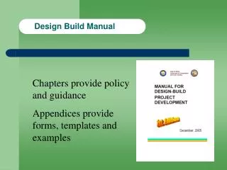
Foundation Block + Reference Design Pre-Qualified/Verified Foundation-IP* Scaleable bus, test, power, IO, clock, timing architectures MEM Hardware IP Processor(s), RTOS(es) and SW architecture CPU FPGA SW IP Programmable Foundry-Specific Pre-Qualification Foundry Targetting Flow The Platform-Based Design ConceptTaking Design Block Reuse to the Next Level Application Space Methodology / Flows: System-level performance evaluation environment Rapid Prototype for End-Customer Evaluation *IP can be hardware (digital or analogue) or software. IP can be hard, soft or ‘firm’ (HW), source or object (SW) SoC Derivative Design Methodologies
DMA DSP CPU MPEG C MEM I O The Platform-Based Design ConceptPlatform Type Examples SONICs Architecture Improv JAZZ Platform { SiliconBackplane™ (patented)
Application Space Platform Specification System Platform Platform Design Space Exploration Architectural Space System House Requirements… exploring and developing on top of SoC Platforms Platform Based Design Objectives • Define the application instance to be implemented to satisfy product requirements defined by consumer • Specify the system platform together with suppliers accordingly • Evaluate top down different instances of SOC platforms
Platform Based Design Objectives Define the SOC platform instance so that multiple instances of applications can be mapped to the same system platform Present this to system customers as SOC Design-Kit and optimally leverage economy of scale for SOC platform instance Provide bottom up instances of SOC platform for evaluation without disclosing the details of the IP Application Space Platform Design Space Exploration System Platform Platform Specification Architectural Space SOC Provider Requirements… designing SoC Platforms and Sub-systems
The VCC Design Flow:An example of Function-Architecture Co-Design
Embedded System Requirements Platform Function Platform Architecture System Integration Performance Analysis and Platform Configuration VCC Front End • Enabling communication within the SOC Design Chain • Design Space Exploration with abstracted Performance Models • Untimed Functional and Performance Verification • Integration Platform Design, Optimization and Configuration Architecture IP CPU/DSPRTOS Bus, Memory HWSW Functional IP C/C++ SDL SPW Simulink Platform Configuration… at theun-clocked, timing-awaresystem level
Embedded System Requirements Platform Function Platform Architecture System Integration Performance Analysis and Platform Configuration VCC Front EndFunctional Integration and Analysis Architecture IP CPU/DSPRTOS Bus, Memory HWSW Functional IP C/C++ SDL SPW Simulink Platform Configuration… at theun-clocked, timing-awaresystem level
Embedded System Requirements Platform Function Platform Architecture System Integration Performance Analysis and Platform Configuration VCC Front EndDefine Architectural Options and Configuration Architecture IP CPU/DSPRTOS Bus, Memory HWSW Functional IP C/C++ SDL SPW Simulink Platform Configuration… at theun-clocked, timing-awaresystem level
Embedded System Requirements Platform Function Platform Architecture System Integration Performance Analysis and Platform Configuration VCC Front EndDefine Function Architecture Mapping Architecture IP CPU/DSPRTOS Bus, Memory HWSW Functional IP C/C++ SDL SPW Simulink Platform Configuration… at theun-clocked, timing-awaresystem level
Embedded System Requirements Platform Function Platform Architecture System Integration Performance Analysis and Platform Configuration VCC Front EndRun Performance Analysis for Platform Configuration Architecture IP CPU/DSPRTOS Bus, Memory HWSW Functional IP C/C++ SDL SPW Simulink Platform Configuration… at theun-clocked, timing-awaresystem level Processor Load Process Gant Chart Analysis Cache Results
CommunicationRefinement, Integration & Synthesis Software Assembly Hardware Assembly Implementation Level Verification Synthesis / Place & Route etc. VCC Backend • Linking System Level Design to Implementation • Fast track to prototyping • Fast track to software development • Design consistency through the design flow Design Export… after initial platform configuration through design refinement and communication synthesis
VCC Model VCC Model to RTOS Protocol Component RTOS VCC Model RTOS to CPU Protocol Component Bus Slave to VCC Model Component CPU Bus Slave CPU to Bus Protocol Component Bus to Bus Slave Component Bus Bus Bus Model CommunicationRefinement, Integration & Synthesis Software Assembly Hardware Assembly Implementation Level Verification Synthesis / Place & Route etc. VCC BackendCommunication Refinement and Synthesis Communication Refinement Communication Synthesis Abstract Token Abstract Token Design Export… after initial platform configuration through design refinement and communication synthesis
VCCSystem ExplorationCommunication Refinement CommunicationRefinement, Integration & Synthesis Flow To Implementation Hardware Top-level System Test Bench Software on RTOS Software Assembly Hardware Assembly Implementation Level Verification Synthesis / Place & Route etc. VCC BackendExport to Implementation (Design and Test Bench) Design Export… after initial platform configuration through design refinement and communication synthesis
Architecture IP CPU/DSPRTOS Bus, Memory HWSW Functional IP C/C++ SDL SPW Simulink Platform Configuration… at theun-clocked, timing-awaresystem level Embedded System Requirements Platform Function Platform Architecture System Integration Design Export… after initial platform configuration through design refinement and communication synthesis Performance Analysis and Platform Configuration CommunicationRefinement, Integration & Synthesis Software Assembly Hardware Assembly Implementation Level Verification Synthesis / Place & Route etc. VCC Flow Summary
Functional Simulation Gate switching defines functionality Combination of gate functionality defines “functionality” of the design Simulation slow in complex systems as huge amounts of events are to be processed Function Functional SimulationGate Level
Functional Simulation Function of system blocks executed General Descriptions C, C++, State Charts, OMI Application specific SPW, Telelogic SDL, Matlab Simulink, ETAS Ascet Functional execution defined as “fire and return” with a OMI 4.0 compliant discrete event simulation infrastructure Simulation is as fast as the abstract, un-timed models simulate SPW StateCharts Function SDL Simulink C++ C Functional SimulationUsing VCC at the System-Level Abstraction
Functional Simulation Gate switching functionality Performance Simulation functionality annotated with intrinsic gate delay interconnect delay modeled from capacity Refinement SDF data is refined after layout is carried out Function Performance SDF andGate Level Library Dt Performance Inter- Connect Capacity Performance SimulationGate Level
Performance Simulation functionality annotated with intrinsic delay models Delay Script and Inline Models, refined after implementation Function Performance Dt VCC Performance SimulationSystem-Level Block Performance Modeling Performance Abstraction Interleaver Dt IP Functional Model Forward Error Correction FEC() { f = x.read(); // FEC function here y.write(r); } Inline Delay Model Scripted Delay Model Annotated IP Functional Model FEC() { f = x.read(); // FEC function part A here __DelayCycles(60*cps); // FEC function part B here __DelayCycles(78*cps); // FEC function part C here __DelayCycles(23*cps); y.write(r); } IP Functional Model Forward Error Correction FEC() { f = x.read(); // FEC function here y.write(r); } FEC on CPU // FEC_ip_implem delay() { input(x); run(); delay(200*cps); output(y); } FEC in slow HW // FEC_ip_implem delay() { input(x); run(); delay(128*cps); output(y); } FEC in fast HW Delay Script // FEC_ip_implem delay() { input(x); run(); delay(64*cps); output(y); }
Value()/Enable() from Behavior 2 Post() from Behavior 1 Shared Memory Communication Pattern Function Sender Receiver RTOS Standard C Library CPU RAM Memory Access Memory Inter- Connect Capacity Performance Pattern Services CPU Port RAM Port ASIC Port Architecture Services Bus Adapter Slave Adapter Bus Adapter Bus Bus Arbiter VCC Performance SimulationSystem Level Block Interconnect Performance Modeling Abstraction
A B Post(5) Value() SemProt_Recv SwMutexes SemProt_Send SemProt_Send mutex_lock;memcpy; signal setEnabled wait;memcpy; signal RTOS Pattern Services Architecture Services MemoryAccess Mem CPU SlaveAdapter BusMaster BusArbiter VCC Performance SimulationEnabled through Architecture Services in VCC Semaphore Protected User Visible write read busIndication busIndication busRequest busRequest arbiterRequest/Release arbiterRequest/Release
Classical Gate Level Technology VCC System Level Technology SDF andGate Level Library IP BlockPerformance Function Performance Performance System Level Library FunctionC, C++,SPW, SDL,Simulink, Statecharts Interleaver Dt D t SPW StateCharts Inter- Connect Capacity InterconnectPerformance IP BlockInterconnectPerformance SDL Simulink C++ C VCC Performance Modeling …… the System Level extension of SDF
Top Down Flow In a pure top down design flow the performance models are “Design Requirements” for functional models They are refined using bottom up techniques in due course throughout the project Bottom Up Flow SOC Provider characterizes IP portfolio, e.g. of a Integration platform using HDL model simulation using software simulation on ISS using benchmarking on SOC IP Functional Model Forward Error Correction FEC() { f = x.read(); // FEC function here y.write(r); } Inline Delay Model Scripted Delay Model Annotated IP Functional Model FEC() { f = x.read(); // FEC function part A here __DelayCycles(60*cps); // FEC function part B here __DelayCycles(78*cps); // FEC function part C here __DelayCycles(23*cps); y.write(r); } IP Functional Model Forward Error Correction FEC() { f = x.read(); // FEC function here y.write(r); } FEC on CPU // FEC_ip_implem delay() { input(x); run(); delay(200*cps); output(y); } FEC in slow HW // FEC_ip_implem delay() { input(x); run(); delay(128*cps); output(y); } FEC in fast HW Delay Script // FEC_ip_implem delay() { input(x); run(); delay(64*cps); output(y); } How to get the performance numbers…IP Block Performance Modeling
Top Down Flow Datasheets for architectural IP information are entered in parameters for architectural services Can be done fast by System Integrator without SOC Provider Refinement with SOC Provider models Bottom Up Flows Architectural IP is profiled using HDL simulation, ISS or silicon and data is entered in VCC architectural services Value()/Enable() from Behavior 2 Post() from Behavior 1 Shared Memory Communication Pattern Sender Receiver RTOS Standard C Library CPU RAM Memory Access Memory Pattern Services CPU Port RAM Port ASIC Port Architecture Services Bus Adapter Slave Adapter Bus Adapter Bus Bus Arbiter How to get the performance numbers… IP Block Interconnect Performance Modeling
Estimation of software performance prior to implementation CPU characterized as Virtual Processor Model Using a Virtual Machine Instruction Set Used for dynamic control SW estimation during performance simulation taking into account bus loading, memory fetching, and register allocation Value True co-design: SW estimation using annotation into C Code (as opposed to to simulation in instruction simulators used in co-verification) Good for early system scheduling, processor load estimation Two orders of magnitude faster than ISS Greater than 80 percent accuracy Enables pre-implementation decision but is not a verification model How to get the performance numbers…Software Estimation for ANSI C code (“Whitebox C”)
Data Book Approach CPU data book information to count cycles and estimate VIM Calibration Suite using “Best Fit” Run Calibration Suite on VIM and ISS Solve a set of linear equations to minimize difference Application Specific Calibration Suite using the “Best Fit” method but use application specific routines for automotive, wireless telecom, multimedia etc. Exact Count on ISS cycle counts exactly derived from ISS run Filter specific commands out (e.g. OPi etc.) How to get the performance numbers…Virtual Processor Model Characterization Methods
Virtual MachineInstruction Set Model LD,3.0 Load from Data Memory LI,1.0 Load from Instr. Mem. ST,3.0 Store to Data Memory OP.c,3.0 Simple ALU Operation OP.s,3.0 OP.i,4.0 OP.l,4.0 OP.f,4.0 OP.d,6.0 MUL.c,9.0 Complex ALU Operation MUL.s,10.0 MUL.i,18.0 MUL.l,22.0 MUL.f,45.0 MUL.d,55.0 DIV.c,19.0 DIV.s,110.0 DIV.i,118.0 DIV.l,122.0 DIV.f,145.0 DIV.d,155.0 IF,5.0 Test and Branch GOTO,2.0 Unconditional Branch SUB,19.0 Branch to Subroutine RET,21.0 Return from Subroutine How to get the performance numbers…Software Estimation for ANSI C code (“Whitebox C”)
Assembler VirtualProcessorModel ld #event,R1 ld #proc,R2 add R1,R2,R3 ld (R3),R4 ldi #0x1, R5 and R4, R5, R6 cmp R0, R6, R7 br R7, LTRUE ba LFALSE Analyse basic blocks compute delays char *event; int proc; if (*(event+proc) & 0x1: 0x0) ... ANSI C Input ld ld op ld li op ts -- br Œ Whitebox C declare ports Generate new C with delay counts Compile generated C and run natively Architecture Characterization Performance Estimation How to get the performance numbers…Software Estimation for ANSI C code (“Whitebox C”)
Architecture Service • The service is the element that defines the functionality of an architecture • A service is coded in C++ and performs a specific role to model architecture, for example: • bus arbitration • memory access • interrupt propagation • etc.
Example of Services ASIC Bus Behavior Post Pattern Sender BusMaster BusArbiter Mem BusSlave Memory
Example of Services • Behavior calls Post, i.e., send a communication • Pattern hears Post and directs ASIC block’s BusMaster to send a communication • BusMaster asks the Bus Block’s BusArbiter for use of the bus • BusArbiter grants the bus, so communication can go to Memory Block • Memory Block’s BusSlave receives communication and forwards to memory • Memory stores communication.
Categories of Services • Pattern Service • services that coordinate the communication of architecture services • Architecture Service • services that define the functionality of architecture • Internal Service • generic, default service used during functional simulation
Pattern Service • A pattern coordinates architectural services that collectively model a communication path from sender to receiver • Patterns are composed of a sender service and a receiver service • Sender service defines Post • Receiver service defines Enabled/Value • Both the sender and receiver service direct the actions of architecture services to send/receive communication Post Pattern Sender Enabled/ Value Pattern Receiver
Basic Example • Let’s assume two behaviors. • b1 and b2 talk to each other: • b1 says Post; b2 says Value • and visa versa
Basic Example (cont) • What does it mean for b1 to talk to b2? • What does it mean for b1 to say Post? • What does it mean for b2 to say Value? • We should consider an architecture to give meaning to b1 and b2. • We should consider how the behavior blocks map to the architecture.
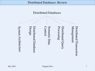
Basic Example (cont) • Let’s assume the following architecture:
Basic Example (cont) • Here we map the behavior to the architecture:
Basic Example (cont) • What do we see in the mapping diagram? • b1 is mapped to software. • b2 is mapped to hardware. • b1 to b2 communication is set to Shared Memory. • b2 to b1 communication is set to to Interrupt Register Mapped. • For simplicity’s sake, we’re focusing on b1-to-b2 communication. • b2 to b1 will be ignored for now. • If b1 talks to b2, how does that look when mapped to an architecture? • What happens when b1 says Post? • What happens when b2 says Value? • Note b1 to b2 is shared memory communication.
Basic Example (cont) • Using Shared Memory, we have the following sequence of communication: 1. b1 writes to memory: b1 è RTOS è CPU è Bus è Mem 2. b2 reads from memory: b2 è ASIC è Bus è Mem
Basic Example (cont) • So b1 talks to b2 through the various architecture components: • b1 says Post and that becomes a write to memory. • b2 says Value and that becomes a read from memory. • What is the underlying mechanism that propagates Post/Value through the architecture? • It’s something called the “service”.