Download
1 / 26
1.4k likes | 4.22k Views
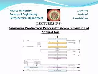
Pharos University جامعه فاروس Faculty of Engineering كلية الهندسة Petrochemical Department قسم البتروكيماويات. LECTURES (5-8) Ammonia Production Process by steam reforming of Natural Gas. 2-Steam reforming Process:.

E N D
Pharos University جامعه فاروس Faculty of Engineering كلية الهندسة Petrochemical Department قسم البتروكيماويات LECTURES (5-8) Ammonia Production Process by steam reforming of Natural Gas
2-Steam reforming Process: • Steam reforming concept based on natural gas is considered to be the most dominating and best available technique for production of ammonia, as the steam reforming process accounts for over 80% of the world’s ammonia production. A-Primary Reforming: • The gas from the desulphurizer is mixed with process steam, usually coming from an extraction turbine, and steam gas mixture is then heated further to 500-600°C in the convection section before entering the primary reformer.
The primary reformer is a furnace in which a multiplicity of tubes of high-nickel chromium alloy filled with nickel-containing reforming catalyst in a big chamber (Radiant box) with burners to provide heat. • The overall reaction is highly endothermic and additional heat is provided by burning of gas in burners provided for the purpose, to raise the temperature to 780-830°C at the reformer outlet.
The composition of gas leaving the reformer is given by close approach to the following chemical equilibrium: CH4 + H2O ↔ CO + 3H2 ∆H = 49.2 kcal/mol CO + H2O ↔ CO2 + H2 ∆H = -9.8 kcal/mol • The heat for the primary reforming is supplied by burning natural gas or other gaseous fuels, in the burners of a radiant box containing catalyst filled tubes.
The flue gas leaving the radiant box has temperature in excess of 900°C, after supplying the high level heat to the reforming process. • About 50-60% of fuel’s heat value is directly used in the process itself. The heat content (waste heat) of the flue-gas is recovered in the reformer convection section, for various process and steam duties.
B-Secondary Reformer • The gas leaving the primary reformer usually contains 5-15% methane (dry basis) and enters the secondary reformer at the bottom. • The object of the secondary reforming step is to complete the conversion of methane to H2, CO, and CO2 and to supply the required proportion of N2 for NH3 synthesis. • This is done by adding air in the amount required to give an N:H atomic ratio of 1:3 in the synthesis gas after the shift conversion step. • The oxygen accompanying the nitrogen in the air burns part of the combustibles (H2, CO, and CH4) in the partially reformed gas, thereby raising the temperature high enough or rapid completion of the reforming.
The process gas is mixed with the air in the mixing chamber of secondary reformer then passed over a nickel catalyst that is supported by a ring-shaped arch made of high-alumina bricks. • The reformer outlet temperature is around 1000°C, and up to 99% of the hydrocarbon feed (to primary reformer) is converted, giving a residual; methane content of 0.2-0.3 (dry gas bases) in the process gas leaving the secondary reformer. • The process gas is cooled to 350-400°C in a waste heat boiler or waste heat boiler/superheater downstream from the secondary reformer.
3- Carbon monoxide conversion process: A- Water-gas shift reaction : • The water-gas shift (WGS) reaction is used to convert carbon monoxide (CO) to carbon dioxide (CO2) and hydrogen (H2) through a reaction with water (H2O) CO + H2O ↔ CO2 + H2 ∆H = -41 kJ/mol • The reaction is exothermic, which means the reaction equilibrium shifts to the right and favors formation of the H2 and CO2 products at lower temperatures. At higher temperatures, the equilibrium shifts to the left, limiting complete conversion of CO to H2. • The reaction is the basis for most of the industrial H2 produced in the world from methane (CH4) in natural gas through steam-methane reforming.
A conventional water-gas shift reactor then uses a metallic catalyst in a heterogeneous gas-phase reaction with CO and steam. • reaction kinetics are faster at elevated temperatures. For this reason, the catalytic water-gas shift reaction is initially carried out in a high-temperature shift (HTS) reactor at 350-370°C. • Conversion in the HTS reactor is limited by the equilibrium composition at the high temperature. • To achieve higher conversions of CO to H2, the gas leaving the HTS reactor is cooled to 200-220°C and passed through approximately 90% of the CO is converted to H2 in the first HTS reactor and 90% of the remaining CO is converted in the LTS reactor.
The process gas from the secondary reformer contains 12-15% CO (dry gas bases) and most of the CO is converted in the shift section according to the reaction: CO + H2O ↔ CO2 + H2 • In the high temperature shift conversion (HTS), the gas is passed through a bed of iron oxide/chromium oxide catalyst at around 400°C, where the CO content is reduced to about 3% (dry gas bases), limited by the shift equilibrium at the actual operating temperature
There is tendency to use copper containing catalyst to increase conversion. The gas from the HTS is cooled and passed through the low temperature shift (LTS) converter. • The LTS is filled with a copper oxide/zinc oxide-based catalyst and operates at about 200-220°C. The residual CO content is important for the efficiency of the process. Therefore, efficiency of shift step in obtaining the highest shift conversion is very important.
4-Carbon dioxide removal • The process gas from the low temperature shift converter contains mainly H2, N2, CO2 (≈ 18%) and excess process steam. • The gas is cooled and most of the excess steam is condensed before it enters the CO2 removal section • The CO2 is removed in a chemical or physical absorption process. The solvents used in chemical absorption process are mainly aqueous amine solutions Mono Ethanolamine (MEA), activated Methyl DiEthanolamine (aMDEA) or hot potassium carbonate solutions. Physical solvents are glycol dimethylethers (Selexol), propylene carbonates and others.
The main advantage of potassium carbonate solution is lower heat requirements for stripping the CO2 from the solvent • The potassium carbonate system operates mainly isothermal-CO2 absorption at high pressure and CO2 release at low pressure. • In the absorption step the pressure is typically about 3.0 MPa (reformer pressure minus pressure losses), and the temperature may be 100°C. The CO2 is absorbed chemically by the conversion of potassium carbonate to bicarbonate.
When the solution pressure is reduced to about atmospheric pressure, part of the CO2 and water vapor escape. CO2 release is assisted by steam stripping. • The steam is raised in the regenerator reboiler heated by the gas from the LTS shift converter; thus, some or most of the heat required by the CO2 removal process is derived from the heat in the incoming gas. • Reaction involved: K2CO3 + CO2 + H2O ↔ 2KHCO3
During absorption, the reaction proceeds from left to right and during regeneration from right to left. The heat of reaction amounts to 340 kcal/Nm3 CO2. • Residual CO2 content are usually in the range (100-1000 ppm), depending on the process used. 5-Methanation: • The gas leaving the CO2 absorption step still contains about 0.3% CO and 0.1% or less CO2. • These oxides must be removed prior to the ammonia synthesis step because they would decrease the activity of the ammonia synthesis catalyst and cause deposition of ammonium carbamate in the synthesis loop.
CO + 3H2 → CH4 + H2O, ΔH25C = - 206.1 kJ/mol • CO2 + 4H2 → CH4 + 2H2O, ΔH20C = -164.9 kJ/mol • These reactions are the reverse of the reformer reactions, and a similar nickel-based catalyst is used. • The methanation step is usually carried out with a gas inlet temperature of 300 - 350°C; therefore, the gas must be preheated to that temperature. • Since the reactions are exothermic, the temperature may rise to 320-400°C at the gas outlet, depending on the CO + CO2 content of the gas. A heat exchanger is commonly used to preheat the incoming gas and cool the exit gas.
6- Compression of synthesis gas • The synthesis gas leaving the methanation step typically contains about 74% H2, 24% N2, 0.8% CH4, and 0.3% , at dry basis. The gas must be compressed to the pressure required by the synthesis step. • centrifugal compressors are now used in most new plants that have capacities of 600-1,800 tpd. Synthesis pressures in these new plants usually are in the range of 15-25 Mpa. • Centrifugal compressors are driven by steam turbines using high-pressure steam generated mainly from hot process gas leaving the secondary reformer. The steam is exhausted at a lower pressure and used in the reforming process and other process steps.
7-Ammonia synthesis: • The synthesis of ammonia is composed of the following reversible reaction of hydrogen and nitrogen. • N2 + 3H2 ↔ 2NH3 • This reaction is exothermic; the net heat of reaction is about 11,000 cal/g mole at 18°C (647 kcal/kg of NH3), assuming NH3 is in the gaseous state. • The metallic iron catalyst is primarily made from magnetite. Fe3O4, that has been promoted using alkali in the form of potash and metals, such as aluminum, calcium, or magnesium • Caution must be taken because the catalyst could undergo thermal degradation.
It could also be permanently poisoned by sulfur, arsenic, phosphorus, chlorine, and heavy hydrocarbons; oxygen-bearing compounds will cause temporary poisoning, which may be reversed if the exposure was only for a short while. • Synthesis pressure, synthesis temperature, space velocity, inlet gas composition, and catalyst particle size all affect ammonia synthesis. • The gas entering the converter consists mainly of gas circulated in the loop with a relatively small amount of fresh synthesis gas called “makeup” gas. The gas entering the converter contains N2 and H2 in a 1:3 ratio plus 10-14% “inerts” and about 2% NH3.
The “inerts” consist mainly of methane, argon, and sometimes helium if the natural gas feedstock contains the element. • Since the inert gas concentration tends to increase as the N2 and H2 are removed, it is necessary to vent a side stream of “purge gas” to keep the inert gas concentration at a tolerable level • Ammonia synthesis converters differ in the type of flow: axial, radial, or cross flow. The reactor is designed for good gas distribution throughout the catalytic bed at minimum pressure drop. The converters also differ in the way temperature control of the reactants is achieved (quench or indirect cooling) and how reaction heat recovery is done.
The gas leaving the converter will contain 12%-18% NH3, depending mainly on the pressure; conversion per pass increases with pressure. • The gas is cooled first by heat exchange with the incoming gas, then by air or water, and finally by refrigeration to condense most of the ammonia as a liquid. • The unreacted gas is recycled with the addition of fresh makeup synthesis gas, thus maintaining the loop pressure.
The purge gas is scrubbed with water to remove ammonia before being used as fuel or before being sent to hydrogen recovery unit. • Vaporizing ammonia is used as a refrigerant in most ammonia plants, to achieve sufficiently low ammonia concentration in the recycled gas. The ammonia vapors are liquefied by compression in the refrigeration compressor