
Electrical Circuit Analysis: Load Impedance Calculation and Power Analysis
E N D
Presentation Transcript
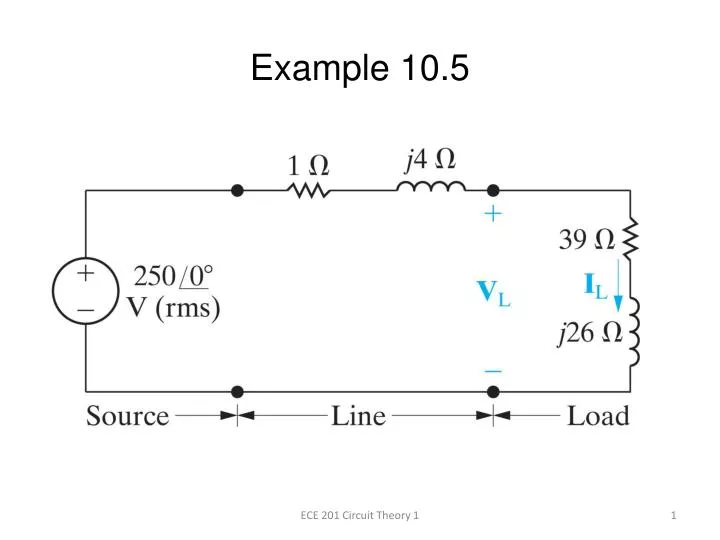
Example 10.5 ECE 201 Circuit Theory 1
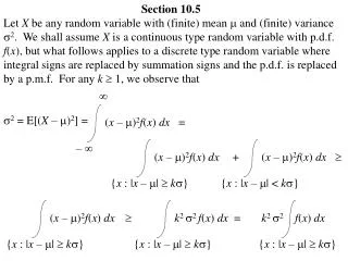
A load having an impedance of 39 + j26 Ω is fed from a voltage source through a line having an impedance of 1 + j4 Ω. The effective, or rms, value of the source voltage is 250 V. Calculate the load current IL and the voltage VL. ECE 201 Circuit Theory 1
Calculate the load current IL and the voltage VL. The line and load impedances are in series across the voltage source, so the load current equals the voltage divided by the total impedance. The load voltage equals the load current multiplied by the load impedance. ECE 201 Circuit Theory 1
Calculate the active and reactive power delivered to the load. Average Power = 975 W Reactive Power = 650 VARS ECE 201 Circuit Theory 1
Calculate the average and reactive power delivered to the line. Reactive Power is positive due to an inductive line reactance ECE 201 Circuit Theory 1
Calculate the average and reactive power supplied by the source Add complex powers delivered to the line and load ECE 201 Circuit Theory 1
Calculate the apparent power The – sign is used whenever the current reference is in the direction of a voltage rise ECE 201 Circuit Theory 1