Chapter 17: Data Link Control and Multiplexing
Chapter 17: Data Link Control and Multiplexing. Business Data Communications, 5e. Flow Control. Necessary when data is being sent faster than it can be processed by receiver Computer to printer is typical setting

Chapter 17: Data Link Control and Multiplexing
E N D
Presentation Transcript
Chapter 17:Data Link Controland Multiplexing Business Data Communications, 5e
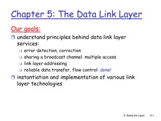
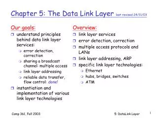
Flow Control • Necessary when data is being sent faster than it can be processed by receiver • Computer to printer is typical setting • Can also be from computer to computer, when a processing program is limited in capacity Business Data Communications, 5e
Error Correction • Two types of errors • Lost frame • Damaged frame • Automatic Repeat reQuest (ARQ) • Error detection • Positive acknowledgment • Retransmission after time-out • Negative acknowledgment and retransmission Business Data Communications, 5e
Data Link Control • Specified flow and error control for synchronous communication • Data link module arranges data into frames, supplemented by control bits • Receiver checks control bits, if data is intact, it strips them Business Data Communications, 5e
High-Level Data Link Control • On transmitting side, HDLC receives data from an application, and delivers it to the receiver on the other side of the link • On the receiving side, HDLC accepts the data and delivers it to the higher level application layer • Both modules exchange control information, encoded into a frame Business Data Communications, 5e
Flag: 01111110, at start and end Address: secondary station (for multidrop configurations) Information: the data to be transmitted Frame check sequence: 16- or 32-bit CRC Control: purpose or function of frame Information frames: contain user data Supervisory frames: flow/error control (ACK/ARQ) Unnumbered frames: variety of control functions (see p.131) HDLC Frame Structure Business Data Communications, 5e
HDLC Operation • Initialization: S-frames specify mode and sequence numbers, U-frames acknowledge • Data Transfer: I-frames exchange user data, S-frames acknowledge and provide flow/error control • Disconnect: U-frames initiate and acknowledge Business Data Communications, 5e
HDLC Examples Business Data Communications, 5e
Multiplexing • Shared use of communication capacity • Commonly used in long-haul communications, on high-capacity fiber, coaxial, or microwave links • Multiplexer combines data from n input lines and transmits over a higher-capacity data link • Demultiplexer accepts multiplexed data stream, separates the data according to channel, and delivers them to the appropriate output lines. Business Data Communications, 5e
Multiplexing Diagram Business Data Communications, 5e
Motivations for Multiplexing • The higher the data rate, the more cost-effective the transmission facility • cost per kbps declines with an increase in the data rate of the transmission facility • cost of transmission and receiving equipment, per kbps, declines with increasing data rate. • Most individual data communicating devices require relatively modest data rate support Business Data Communications, 5e
Frequency Division Multiplexing (FDM) • Requires analog signaling & transmission • Total bandwidth = sum of input bandwidths + guardbands • Modulates signals so that each occupies a different frequency band • Standard for radio broadcasting, analog telephone network, and television (broadcast, cable, & satellite) Business Data Communications, 5e
Wavelength Division Multiplexing • Form of FDM used when multiple beams of light at different frequencies are transmitted on the same optical fiber • Most WDM systems operate in the 1550-nm range. In early systems, 200 MHz was allocated to each channel, but today most WDM systems use 50-GHz spacing • dense wavelength division multiplexing (DWDM) connotes the use of more channels, more closely spaced (≤200Ghz), than ordinary WDM Business Data Communications, 5e
FDM Example: ADSL • ADSL uses frequency-division modulation (FDM) to exploit the 1-MHz capacity of twisted pair. • Asymmetric because ADSL provides more capacity downstream (from the carrier’s central office to the customer’s site) than upstream (from customer to carrier). Business Data Communications, 5e
3 Elements of ADSL Strategy • Reserve lowest 25 kHz for voice, known as POTS • Use echo cancellation or FDM to allocate a small upstream band and a larger downstream band • Use FDM within the upstream and downstream bands, using “discrete multitone” Business Data Communications, 5e
Echo Cancellation • Entire frequency band for the upstream channel overlaps the lower portion of the downstream channel • Advantages • The higher the frequency, the greater the attenuation. • More flexible for changing upstream capacity • Disdvantages • Need for echo cancellation logic on both ends of line Business Data Communications, 5e
Discrete Multitone (DMT) • Uses multiple carrier signals at different frequencies, sending some of the bits on each channel. • Transmission band (upstream or downstream) is divided into a number of 4-kHz subchannels. • Modem sends out test signals on each subchannel to determine the signal to noise ratio; it then assigns more bits to better quality channels and fewer bits to poorer quality channels. Business Data Communications, 5e
Synchronous Time-Division Multiplexing (TDM) • Used in digital transmission • Requires data rate of the medium to exceed data rate of signals to be transmitted • Signals “take turns” over medium • Slices of data are organized into frames • Used in the modern digital telephone system • US, Canada, Japan: DS-0, DS-1 (T-1), DS-3 (T-3), ... • Europe, elsewhere: E-1, E3, … Business Data Communications, 5e
Digital Carrier Systems • Long-distance carrier system designed to transmit voice signals over high-capacity transmission links (e.g. optical fiber, coaxial cable, and microwave) • Evolution of these networks to digital involved adoption of synchronous TDM transmission structures Business Data Communications, 5e
DS-1 Transmission Format • Multiplexes 24 channels • Voice transmission • Frame contains 8 bits per channel plus a framing bit for 24 8 + 1 = 193 bits • Signal digitized with PCM at 8000 samples/second • Data rate of 8000 193 = 1.544 Mbps • Data transmission • 23 channels of data are provided • Last channel position reserved for special sync byte • Mixed voice and data uses all 24 channels Business Data Communications, 5e
DS-1 Illustration Business Data Communications, 5e
T-1 Facilities • Transmission facilities supporting DS-1 • Often used for leased dedicated transmission between customer premises • Private voice networks • Private data network • Video teleconferencing • High-speed digital facsimile • Internet access Business Data Communications, 5e
SONET/SDH • SONET (Synchronous Optical Network) is an optical transmission interface proposed by BellCore and standardized by ANSI. • Synchronous Digital Hierarchy (SDH), a compatible version, has been published by ITU-T • Specifications for taking advantage of the high-speed digital transmission capability of optical fiber. Business Data Communications, 5e
SONET/SDH Signal Hierarchy Business Data Communications, 5e
STS-1 and STM-N Frames Business Data Communications, 5e