The Data Link Layer
The Data Link Layer. Chapter 3. Data Link Layer Design Issues. Network layer services Framing Error control Flow control. Data Link Layer. Algorithms for achieving: Reliable, + Efficient, communication of a whole units – frames (as opposed to bits – Physical Layer) between two machines.


The Data Link Layer
E N D
Presentation Transcript
The Data Link Layer Chapter 3
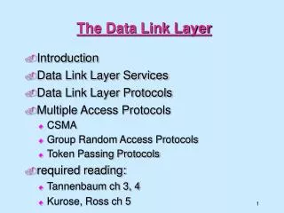
Data Link Layer Design Issues • Network layer services • Framing • Error control • Flow control
Data Link Layer • Algorithms for achieving: • Reliable, + • Efficient, communication of a whole units – frames (as opposed to bits – Physical Layer) between two machines. • Two machines are connected by a communication channel that acts conceptually like a wire (e.g., telephone line, coaxial cable, or wireless channel). • Essential property of a channel that makes it “wire-like” connection is that the bits are delivered in exactly the same order in which they are sent.
Data Link Layer For ideal channel (no distortion, unlimited bandwidth and no delay) the job of data link layer would be trivial. However, limited bandwidth, distortions and delay makes this job very difficult.
Data Link Layer Design Issues • Physical layer delivers bits of information to and from data link layer. The functions of Data Link Layer are: • Providing a well-defined service interface to the network layer. • Dealing with transmission errors. • Regulating the flow of data so that slow receivers are not swamped by fast senders. • Data Link layer • Takes the packets from Physical layer, and • Encapsulates them into frames
Data Link Layer Design Issues • Each frame has a • frame header – a field for holding the packet, and • frame trailer. • Frame Management is what Data Link Layer does. • See figure in the next slide:
Packets and Frames Relationship between packets and frames.
Services Provided to the Network Layer • Principal Service Function of the data link layer is to transfer the data from the network layer on the source machine to the network layer on the destination machine. • Process in the network layer that hands some bits to the data link layer for transmission. • Job of data link layer is to transmit the bits to the destination machine so they can be handed over to the network layer there (see figure in the next slide).
Network Layer Services (a) Virtual communication. (b) Actual communication.
Possible Services Offered Unacknowledged connectionless service. Acknowledged connectionless service. Acknowledged connection-oriented service.
Unacknowledged Connectionless Service It consists of having the source machine send independent frames to the destination machine without having the destination machine acknowledge them. Example: Ethernet, Voice over IP, etc. in all the communication channel were real time operation is more important that quality of transmission.
Acknowledged Connectionless Service Each frame send by the Data Link layer is acknowledged and the sender knows if a specific frame has been received or lost. Typically the protocol uses a specific time period that if has passed without getting acknowledgment it will re-send the frame. This service is useful for commutation when an unreliable channel is being utilized (e.g., 802.11 WiFi). Network layer does not know frame size of the packets and other restriction of the data link layer. Hence it becomes necessary for data link layer to have some mechanism to optimize the transmission.
Acknowledged Connection Oriented Service • Source and Destination establish a connection first. • Each frame sent is numbered • Data link layer guarantees that each frame sent is indeed received. • It guarantees that each frame is received only once and that all frames are received in the correct order. • Examples: • Satellite channel communication, • Long-distance telephone communication, etc.
Acknowledged Connection Oriented Service • Three distinct phases: • Connection is established by having both side initialize variables and counters needed to keep track of which frames have been received and which ones have not. • One or more frames are transmitted. • Finally, the connection is released – freeing up the variables, buffers, and other resources used to maintain the connection.
Framing • To provide service to the network layer the data link layer must use the service provided to it by physical layer. • Stream of data bits provided to data link layer is not guaranteed to be without errors. • Errors could be: • Number of received bits does not match number of transmitted bits (deletion or insertion) • Bit Value • It is up to data link layer to correct the errors if necessary.
Framing • Transmission of the data link layer starts with breaking up the bit stream • into discrete frames • Computation of a checksum for each frame, and • Include the checksum into the frame before it is transmitted. • Receiver computes its checksum error for a receiving frame and if it is different from the checksum that is being transmitted will have to deal with the error. • Framing is more difficult than one could think!
Framing Methods Byte count. Flag bytes with byte stuffing. Flag bits with bit stuffing. Physical layer coding violations.
Byte Count Framing Method • It uses a field in the header to specify the number of bytes in the frame. • Once the header information is being received it will be used to determine end of the frame. • See figure in the next slide: • Trouble with this algorithm is that when the count is incorrectly received the destination will get out of synch with transmission. • Destination may be able to detect that the frame is in error but it does not have a means (in this algorithm) how to correct it.
Framing (1) A byte stream. (a) Without errors. (b) With one error.
Flag Bytes with Byte Staffing Framing Method This methods gets around the boundary detection of the frame by having each appended by the frame start and frame end special bytes. If they are the same (beginning and ending byte in the frame) they are called flag byte. In the next slide figure this byte is shown as FLAG. If the actual data contains a byte that is identical to the FLAG byte (e.g., picture, data stream, etc.) the convention that can be used is to have escape character inserted just before the “FLAG” character.
Framing (2) A frame delimited by flag bytes. Four examples of byte sequences before and after byte stuffing.
Flag Bits with Bit Stuffing Framing Method • This methods achieves the same thing as Byte Stuffing method by using Bits (1) instead of Bytes (8 Bits). • It was developed for High-level Data Link Control (HDLC) protocol. • Each frames begins and ends with a special bit patter: • 01111110 or 0x7E <- Flag Byte • Whenever the sender’s data link layer encounters five consecutive 1s in the data it automatically stuffs a 0 bit into the outgoing bit stream. • USB uses bit stuffing.
Framing (3) Bit stuffing. (a) The original data. (b) The data as they appear on the line. (c) The data as they are stored in the receiver’s memory after destuffing.
Framing Many data link protocols use a combination of presented methods for safety. For example in Ethernet and 802.11 each frame begin with a well-defined pattern called a preamble. Preamble is typically 72 bits long. It is then followed by a length fileld.
Error Control • After solving the marking of the frame with start and end the data link layer has to handle eventual errors in transmission or detection. • Ensuring that all frames are delivered to the network layer at the destination and in proper order. • Unacknowledged connectionless service: it is OK for the sender to output frames regardless of its reception. • Reliable connection-oriented service: it is NOT OK.
Error Control • Reliable connection-oriented service usually will provide a sender with some feedback about what is happening at the other end of the line. • Receiver Sends Back Special Control Frames. • If the Sender Receives positive Acknowledgment it will know that the frame has arrived safely. • Timer and Frame Sequence Number for the Sender is Necessary to handle the case when there is no response (positive or negative) from the Receiver .
Flow Control • Important Design issue for the cases when the sender is running on a fast powerful computer and receiver is running on a slow low-end machine. • Two approaches: • Feedback-based flow control • Rate-based flow control
Feedback-based Flow Control Receiver sends back information to the sender giving it permission to send more data, or Telling sender how receiver is doing.
Rate-based Flow Control Built in mechanism that limits the rate at which sender may transmit data, without the need for feedback from the receiver.
Error Detection and Correction • Two basic strategies to deal with errors: • Include enough redundant information to enable the receiver to deduce what the transmitted data must have been.Error correcting codes. • Include only enough redundancy to allow the receiver to deduce that an error has occurred (but not which error).Error detecting codes.
Error Detection and Correction • Error codes are examined in Link Layer because this is the first place that we have run up against the problem of reliability transmitting groups of bits. • Codes are reused because reliability is an overall concern. • The error correcting code are also seen in the physical layer for noise channels. • Commonly they are used in link, network and transport layer.
Error Detection and Correction Error codes have been developed after long fundamental research conducted in mathematics. Many protocol standards get codes from the large field in mathematics.
Error Detection & Correction Code (1) Hamming codes. Binary convolutional codes. Reed-Solomon codes. Low-Density Parity Check codes.
Error Detection & Correction Code • All the codes presented in previous slide add redundancy to the information that is being sent. • A frame consists of • m data bits (message) and • r redundant bits (check). • Block code - the r check bits are computed solely as function of the m data bits with which they are associated. • Systemic code– the m data bits are send directly along with the check bits. • Linear code – the r check bits are computed as a linear function of the m data bits.
Error Detection & Correction Code n – total length of a block (i.e., n = m + r) (n, m) – code n – bit codeword containing n bits. m/n – code rate (range ½ for noisy channel and close to 1 for high-quality channel).
Error Detection & Correction Code Example Transmitted: 10001001 Received: 10110001 XOR operation gives number of bits that are different. XOR: 00111000 Number of bit positions in which two codewords differ is called Hamming Distance. It shows that two codes are d distance apart, and it will require d errors to convert one into the other.
Error Detection & Correction Code All 2m possible data messages are legal, but due to the way the check bits are computers not all 2n possible code words are used. Only small fraction of 2m/2n=1/2r are possible will be legal codewords. The error-detecting and error-correcting codes of the block code depend on this Hamming distance. To reliably detect d error, one would need a distance d+1 code. To correct d error, one would need a distance 2d+1 code.
Error Detection & Correction Code All 2m possible data messages are legal, but due to the way the check bits are computers not all 2n possible code words are used. Only small fraction of 2m/2n=1/2r are possible will be legal codewords. The error-detecting and error-correcting codes of the block code depend on this Hamming distance. To reliably detect d error, one would need a distance d+1 code. To correct d error, one would need a distance 2d+1 code.
Error Detection & Correction Code Example: • 4 valid codes: • 0000000000 • 0000011111 • 1111100000 • 1111111111 • Minimal Distance of this code is 5 => can correct and double errors and it detect quadruple errors. • 0000000111 => single or double – bit error. Hence the receiving end must assume the original transmission was 0000011111. • 0000000000 => had triple error that was received as 0000000111 it would be detected in error.
Error Detection & Correction Code • One cannot perform double errors and at the same time detect quadruple errors. • Error correction requires evaluation of each candidate codeword which may be time consuming search. • Through design this search time can be minimized. • In theory if n = m + r, this requirement becomes: • (m + r + 1) ≤ 2r
Hamming Code Codeword: b1 b2 b3 b4 …. Check bits: The bits that are powers of 2 (p1, p2, p4, p8, p16, …). The rest of bits (m3, m5, m6, m7, m9, …) are filled with m data bits. Example of the Hamming code with m = 7 data bits and r= 4 check bits is given in the next slide.
The Hamming Code Consider a message having four data bits (D) which is to be transmitted as a 7-bit codeword by adding three error control bits. This would be called a (7,4) code. The three bits to be added are three EVEN Parity bits (P), where the parity of each is computed on different subsets of the message bits as shown below.
Hamming Code Why Those Bits? - The three parity bits (1,2,4) are related to the data bits (3,5,6,7) as shown at right. In this diagram, each overlapping circle corresponds to one parity bit and defines the four bits contributing to that parity computation. For example, data bit 3 contributes to parity bits 1 and 2. Each circle (parity bit) encompasses a total of four bits, and each circle must have EVEN parity. Given four data bits, the three parity bits can easily be chosen to ensure this condition. It can be observed that changing any one bit numbered 1..7 uniquely affects the three parity bits. Changing bit 7 affects all three parity bits, while an error in bit 6 affects only parity bits 2 and 4, and an error in a parity bit affects only that bit. The location of any single bit error is determined directly upon checking the three parity circles.
Hamming Code For example, the message 1101 would be sent as 1100110, since:
Hamming Codes When these seven bits are entered into the parity circles, it can be confirmed that the choice of these three parity bits ensures that the parity within each circle is EVEN, as shown here.
Hamming Code It may now be observed that if an error occurs in any of the seven bits, that error will affect different combinations of the three parity bits depending on the bit position. For example, suppose the above message 1100110 is sent and a single bit error occurs such that the codeword 1110110 is received: transmitted message received message 1 1 0 0 1 1 0 ------------> 1 1 1 0 1 1 0 BIT: 7 6 5 4 3 2 1 BIT: 7 6 5 4 3 2 1 The above error (in bit 5) can be corrected by examining which of the three parity bits was affected by the bad bit:
Hamming Code In fact, the bad parity bits labeled 101 point directly to the bad bit since 101 binary equals 5. Examination of the 'parity circles' confirms that any single bit error could be corrected in this way. The value of the Hamming code can be summarized: Detection of 2 bit errors (assuming no correction is attempted); Correction of single bit errors; Cost of 3 bits added to a 4-bit message. The ability to correct single bit errors comes at a cost which is less than sending the entire message twice. (Recall that simply sending a message twice accomplishes no error correction.)
Error Detection Codes (2) Example of an (11, 7) Hamming code correcting a single-bit error.