Microprocessors
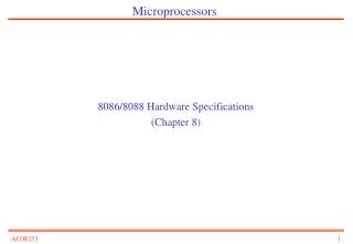
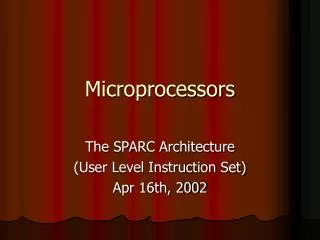
Microprocessors. source. gate. Conducts if gate=1. drain. 1. gate. oxide. IC package. IC. source. channel. drain. Silicon substrate. CMOS transistor on silicon. Transistor The basic electrical component in digital systems Acts as an on/off switch

Microprocessors
E N D
Presentation Transcript
source gate Conducts if gate=1 drain 1 gate oxide IC package IC source channel drain Silicon substrate CMOS transistor on silicon • Transistor • The basic electrical component in digital systems • Acts as an on/off switch • Voltage at “gate” controls whether current flows from source to drain • Don’t confuse this “gate” with a logic gate
source source gate Conducts if gate=0 gate Conducts if gate=1 drain drain pMOS nMOS 1 1 1 x x y x F = x' y F = (xy)' x F = (x+y)' y 0 x y 0 0 NOR gate inverter NAND gate CMOS transistor implementations • Complementary Metal Oxide Semiconductor • We refer to logic levels • Typically 0 is 0V, 1 is 5V • Two basic CMOS types • nMOS conducts if gate=1 • pMOS conducts if gate=0 • Hence “complementary” • Basic gates • Inverter, NAND, NOR
x x F F x x x F F y x F x x x x x x y y y y y y F F F F F F y 0 0 0 1 F y 0 0 0 0 0 0 0 0 0 0 0 0 1 0 1 0 0 1 1 1 1 0 0 0 0 0 0 0 1 1 1 1 1 1 0 1 1 0 0 1 1 1 1 1 1 1 0 0 0 0 0 0 1 1 0 0 1 0 1 1 1 1 1 1 1 1 1 1 1 1 0 0 1 1 0 1 x x x F x F F F y y y F = x y XNOR Basic logic gates F = x Driver F = x y AND F = x + y OR F = x y XOR F = x’ Inverter F = (x y)’ NAND F = (x+y)’ NOR
B) Truth table C) Output equations D) Minimized output equations Outputs Inputs y bc y = a'bc + ab'c' + ab'c + abc' + abc a b c y z 00 01 11 10 a 0 0 0 1 0 0 0 0 0 0 0 0 1 0 1 1 1 1 1 1 z = a'b'c + a'bc' + ab'c + abc' + abc 0 1 0 0 1 0 1 1 1 0 y = a + bc z 1 0 0 1 0 bc 00 01 11 10 1 0 1 1 1 a 0 0 1 0 1 1 1 0 1 1 1 1 1 1 1 1 0 1 1 1 E) Logic Gates z = ab + b’c + bc’ a y b c z Combinational logic design A) Problem description y is 1 if a is to 1, or b and c are 1. z is 1 if b or c is to 1, but not both, or if all are 1.
A B I1 I0 I(m-1) n n n … n bit, m function ALU S0 n-bit, m x 1 Multiplexor S0 … … S(log m) n S(log m) n O O O = I0 if S=0..00 I1 if S=0..01 … I(m-1) if S=1..11 less = 1 if A<B equal =1 if A=B greater=1 if A>B O = A op B op determined by S. O0 =1 if I=0..00 O1 =1 if I=0..01 … O(n-1) =1 if I=1..11 sum = A+B (first n bits) carry = (n+1)’th bit of A+B A B I0 A I(log n -1) B n n … n log n x n Decoder n-bit Adder n-bit Comparator With enable input e all O’s are 0 if e=0 With carry-in input Ci sum = A + B + Ci May have status outputs carry, zero, etc. … n O(n-1) O1 O0 carry sum less equal greater Combinational components
I n load shift n-bit Register n-bit Shift register n-bit Counter clear I Q n n Q Q Sequential components Q = lsb - Content shifted - I stored in msb Q = 0 if clear=1, I if load=1 and clock=1, Q(previous) otherwise. Q = 0 if clear=1, Q(prev)+1 if count=1 and clock=1.
Gated R-S Latch (clocked S-R flip-flop) Enb = 1, latch closed (outputs unchanged) Enb = 0, enabled (outputs depend on inputs)
J-K Flip-flop How to eliminate the forbidden state? Idea: use output feedback to guarantee that R and S are never both one J, K both one yields toggle Characteristic Equation: Q+ = Q K + Q J
D) State Table (Moore-type) C) Implementation Model B) State Diagram Outputs Inputs Q1 Q0 a I1 I0 x x a Combinational logic 0 0 0 0 0 x=1 x=0 a=0 a=0 0 I1 0 0 1 0 1 0 3 a=1 0 1 0 0 1 I0 0 0 1 1 1 0 a=1 a=1 1 0 0 1 0 0 Q1 Q0 1 0 1 1 1 1 2 1 1 0 1 1 1 a=1 1 1 1 0 0 State register a=0 a=0 x=0 x=0 I0 I1 Sequential logic design • Given this implementation model • Sequential logic design quickly reduces to combinational logic design A) Problem Description You want to construct a clock divider. Slow down your pre-existing clock so that you output a 1 for every four clock cycles
E) Minimized Output Equations F) Combinational Logic Q1Q0 I1 00 01 11 10 a 0 0 1 1 a 0 I1 = Q1’Q0a + Q1a’ + Q1Q0’ x 0 1 0 1 1 Q1Q0 I0 00 01 11 10 a 0 1 1 0 I1 0 I0 = Q0a’ + Q0’a 1 0 0 1 1 x I0 Q1Q0 00 01 11 10 a 0 0 1 0 x = Q1Q0 0 0 0 1 0 Q1 Q0 1 Sequential logic design (cont.)
Processor Control unit Datapath ALU Controller Control /Status Registers PC IR I/O Memory Basic Architecture • Control unit and datapath • Note similarity to single-purpose processor • Key differences • Datapath is general • Control unit doesn’t store the algorithm – the algorithm is “programmed” into the memory
+1 Datapath Operations • Load • Read memory location into register Processor Control unit Datapath ALU • ALU operation • Input certain registers through ALU, store back in register Controller Control /Status Registers • Store • Write register to memory location 10 11 PC IR I/O ... Memory 10 11 ...
Processor Control unit Datapath ALU Controller Control /Status Registers PC IR R0 R1 I/O ... Memory 100 load R0, M[500] 500 10 101 inc R1, R0 501 ... 102 store M[501], R1 Control Unit • Control unit: configures the datapath operations • Sequence of desired operations (“instructions”) stored in memory – “program” • Instruction cycle – broken into several sub-operations, each one clock cycle, e.g.: • Fetch: Get next instruction into IR • Decode: Determine what the instruction means • Fetch operands: Move data from memory to datapath register • Execute: Move data through the ALU • Store results: Write data from register to memory
Control Unit Sub-Operations • Fetch • Get next instruction into IR • PC: program counter, always points to next instruction • IR: holds the fetched instruction Processor Control unit Datapath ALU Controller Control /Status Registers PC IR 100 R0 R1 load R0, M[500] I/O ... Memory 100 load R0, M[500] 500 10 101 inc R1, R0 501 ... 102 store M[501], R1
Control Unit Sub-Operations • Decode • Determine what the instruction means Processor Control unit Datapath ALU Controller Control /Status Registers PC IR 100 R0 R1 load R0, M[500] I/O ... Memory 100 load R0, M[500] 500 10 101 inc R1, R0 501 ... 102 store M[501], R1
Control Unit Sub-Operations • Fetch operands • Move data from memory to datapath register Processor Control unit Datapath ALU Controller Control /Status Registers 10 PC IR 100 R0 R1 load R0, M[500] I/O ... Memory 100 load R0, M[500] 500 10 101 inc R1, R0 501 ... 102 store M[501], R1
Control Unit Sub-Operations • Execute • Move data through the ALU • This particular instruction does nothing during this sub-operation Processor Control unit Datapath ALU Controller Control /Status Registers 10 PC IR 100 R0 R1 load R0, M[500] I/O ... Memory 100 load R0, M[500] 500 10 101 inc R1, R0 501 ... 102 store M[501], R1
Control Unit Sub-Operations • Store results • Write data from register to memory • This particular instruction does nothing during this sub-operation Processor Control unit Datapath ALU Controller Control /Status Registers 10 PC IR 100 R0 R1 load R0, M[500] I/O ... Memory 100 load R0, M[500] 500 10 101 inc R1, R0 501 ... 102 store M[501], R1
Processor Fetch ops Store results Control unit Datapath Fetch Decode Exec. ALU Controller Control /Status Registers 10 PC IR R0 R1 load R0, M[500] I/O ... Memory 100 load R0, M[500] 500 10 101 inc R1, R0 501 ... 102 store M[501], R1 Instruction Cycles PC=100 clk 100
Processor Control unit Datapath ALU Controller +1 Control /Status Registers Fetch ops Store results Fetch Decode Exec. 11 PC IR R0 R1 inc R1, R0 I/O ... Memory 100 load R0, M[500] 500 10 101 inc R1, R0 501 ... 102 store M[501], R1 Instruction Cycles PC=100 Fetch ops Store results Fetch Decode Exec. clk PC=101 clk 10 101
Processor Control unit Datapath ALU Controller Control /Status Registers PC IR R0 R1 store M[501], R1 Fetch ops Store results Fetch Decode Exec. I/O ... Memory 100 load R0, M[500] 500 10 101 inc R1, R0 501 11 ... 102 store M[501], R1 Instruction Cycles PC=100 Fetch ops Store results Fetch Decode Exec. clk PC=101 Fetch ops Store results Fetch Decode Exec. clk 10 11 102 PC=102 clk
Processor Control unit Datapath ALU Controller Control /Status Registers PC IR I/O Memory Architectural Considerations • N-bit processor • N-bit ALU, registers, buses, memory data interface • Embedded: 8-bit, 16-bit, 32-bit common • Desktop/servers: 32-bit, even 64 • PC size determines address space
Processor Control unit Datapath ALU Controller Control /Status Registers PC IR I/O Memory Architectural Considerations • Clock frequency • Inverse of clock period • Must be longer than longest register to register delay in entire processor • Memory access is often the longest
Pipelining: Increasing Instruction Throughput Wash 1 2 3 4 5 6 7 8 1 2 3 4 5 6 7 8 Non-pipelined Pipelined Dry 1 2 3 4 5 6 7 8 1 2 3 4 5 6 7 8 non-pipelined dish cleaning Time pipelined dish cleaning Time Fetch-instr. 1 2 3 4 5 6 7 8 Decode 1 2 3 4 5 6 7 8 Fetch ops. 1 2 3 4 5 6 7 8 Pipelined Execute 1 2 3 4 5 6 7 8 Instruction 1 Store res. 1 2 3 4 5 6 7 8 Time pipelined instruction execution
Superscalar and VLIW Architectures • Performance can be improved by: • Faster clock (but there’s a limit) • Pipelining: slice up instruction into stages, overlap stages • Multiple ALUs to support more than one instruction stream • Superscalar • Scalar: non-vector operations • Fetches instructions in batches, executes as many as possible • May require extensive hardware to detect independent instructions • VLIW: each word in memory has multiple independent instructions • Relies on the compiler to detect and schedule instructions • Currently growing in popularity
Processor Processor Program memory Data memory Memory (program and data) Harvard Princeton Two Memory Architectures • Princeton • Fewer memory wires • Harvard • Simultaneous program and data memory access
Fast/expensive technology, usually on the same chip Processor Cache Memory Slower/cheaper technology, usually on a different chip Cache Memory • Memory access may be slow • Cache is small but fast memory close to processor • Holds copy of part of memory • Hits and misses
Programmer’s View • Programmer doesn’t need detailed understanding of architecture • Instead, needs to know what instructions can be executed • Two levels of instructions: • Assembly level • Structured languages (C, C++, Java, etc.) • Most development today done using structured languages • But, some assembly level programming may still be necessary • Drivers: portion of program that communicates with and/or controls (drives) another device • Often have detailed timing considerations, extensive bit manipulation • Assembly level may be best for these
Instruction 1 opcode operand1 operand2 Instruction 2 opcode operand1 operand2 Instruction 3 opcode operand1 operand2 Instruction 4 opcode operand1 operand2 ... Assembly-Level Instructions • Instruction Set • Defines the legal set of instructions for that processor • Data transfer: memory/register, register/register, I/O, etc. • Arithmetic/logical: move register through ALU and back • Branches: determine next PC value when not just PC+1
A Simple (Trivial) Instruction Set Assembly instruct. First byte Second byte Operation MOV Rn, direct 0000 Rn direct Rn = M(direct) MOV direct, Rn 0001 Rn direct M(direct) = Rn Rm MOV @Rn, Rm 0010 Rn M(Rn) = Rm MOV Rn, #immed. 0011 Rn immediate Rn = immediate ADD Rn, Rm 0100 Rn Rm Rn = Rn + Rm SUB Rn, Rm 0101 Rn Rm Rn = Rn - Rm JZ Rn, relative 0110 Rn relative PC = PC+ relative (only if Rn is 0) opcode operands
Addressing mode Register-file contents Memory contents Operand field Immediate Data Register-direct Register address Data Register indirect Register address Memory address Data Direct Memory address Data Indirect Memory address Memory address Data Addressing Modes
C program Equivalent assembly program 0 MOV R0, #0; // total = 0 1 MOV R1, #10; // i = 10 2 MOV R2, #1; // constant 1 int total = 0; for (int i=10; i!=0; i--) total += i; // next instructions... 3 MOV R3, #0; // constant 0 Loop: JZ R1, Next; // Done if i=0 5 ADD R0, R1; // total += i 6 SUB R1, R2; // i-- 7 JZ R3, Loop; // Jump always Next: // next instructions... Sample Programs • Try some others • Handshake: Wait until the value of M[254] is not 0, set M[255] to 1, wait until M[254] is 0, set M[255] to 0 (assume those locations are ports). • (Harder) Count the occurrences of zero in an array stored in memory locations 100 through 199.
Application-Specific Instruction-Set Processors (ASIPs) • General-purpose processors • Sometimes too general to be effective in demanding application • e.g., video processing – requires huge video buffers and operations on large arrays of data, inefficient on a GPP • But single-purpose processor has high NRE, not programmable • ASIPs – targeted to a particular domain • Contain architectural features specific to that domain • e.g., embedded control, digital signal processing, video processing, network processing, telecommunications, etc. • Still programmable
A Common ASIP: Microcontroller • For embedded control applications • Reading sensors, setting actuators • Mostly dealing with events (bits): data is present, but not in huge amounts • e.g., VCR, disk drive, digital camera (assuming SPP for image compression), washing machine, microwave oven • Microcontroller features • On-chip peripherals • Timers, analog-digital converters, serial communication, etc. • Tightly integrated for programmer, typically part of register space • On-chip program and data memory • Direct programmer access to many of the chip’s pins • Specialized instructions for bit-manipulation and other low-level operations
Another Common ASIP: Digital Signal Processors (DSP) • For signal processing applications • Large amounts of digitized data, often streaming • Data transformations must be applied fast • e.g., cell-phone voice filter, digital TV, music synthesizer • DSP features • Several instruction execution units • Multiple-accumulate single-cycle instruction, other instrs. • Efficient vector operations – e.g., add two arrays • Vector ALUs, loop buffers, etc.
Trend: Even More Customized ASIPs • In the past, microprocessors were acquired as chips • Today, we increasingly acquire a processor as Intellectual Property (IP) • e.g., synthesizable VHDL model • Opportunity to add a custom datapath hardware and a few custom instructions, or delete a few instructions • Can have significant performance, power and size impacts • Problem: need compiler/debugger for customized ASIP • Remember, most development uses structured languages • One solution: automatic compiler/debugger generation • e.g., www.tensillica.com • Another solution: retargettable compilers • e.g., www.improvsys.com (customized VLIW architectures)
Programmer Considerations • Program and data memory space • Embedded processors often very limited • e.g., 64 Kbytes program, 256 bytes of RAM (expandable) • Registers: How many are there? • Only a direct concern for assembly-level programmers • I/O • How communicate with external signals? • Interrupts
Selecting a Microprocessor • Issues • Technical: speed, power, size, cost • Other: development environment, prior expertise, licensing, etc. • Speed: how evaluate a processor’s speed? • Clock speed – but instructions per cycle may differ • Instructions per second – but work per instr. may differ • Dhrystone: Synthetic benchmark, developed in 1984. Dhrystones/sec. • MIPS: 1 MIPS = 1757 Dhrystones per second (based on Digital’s VAX 11/780). A.k.a. Dhrystone MIPS. Commonly used today. • So, 750 MIPS = 750*1757 = 1,317,750 Dhrystones per second • SPEC: set of more realistic benchmarks, but oriented to desktops • EEMBC – EDN Embedded Benchmark Consortium, www.eembc.org • Suites of benchmarks: automotive, consumer electronics, networking, office automation, telecommunications
General Purpose Processors Sources: Intel, Motorola, MIPS, ARM, TI, and IBM Website/Datasheet; Embedded Systems Programming, Nov. 1998
Microprocessor Architecture Overview • If you are using a particular microprocessor, now is a good time to review its architecture