Download

1 / 15
150 likes | 281 Views
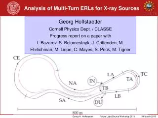
Analysis of Multi-Turn ERLs for X-ray Sources. Georg Hoffstaetter Cornell Physics Dept. / CLASSE Progress report on a paper with I. Bazarov, S. Belomestnyk, J. Crittenden, M. Ehrlichman, M. Liepe, C. Mayes, S. Peck, M. Tigner. BBU: Collective Instabilities. Higher Order Modes.

E N D
Analysis of Multi-Turn ERLs for X-ray Sources Georg HoffstaetterCornell Physics Dept. / CLASSEProgress report on a paper withI. Bazarov, S. Belomestnyk, J. Crittenden, M. Ehrlichman, M. Liepe, C. Mayes, S. Peck, M. Tigner
BBU: Collective Instabilities Higher Order Modes
BBU: Collective Instabilities Higher Order Modes
BBU: Collective Instabilities Higher Order Modes
Optimize shape of cavity (>70 parameter…) to minimize cryogenic losses and maximize limits to beam current Understand sensitivity of optimized design to fabrication errors; find “sloppy” parameter! Main Linac Cavity Optimization Higher-Order-modes Red: Optimized cavity; blue: perturbed cavities
Cavities with misalignments R/Q and Q in cavities with misalignments can be significantly worse then expected, but orders of magnitude. (Here for 1/16mm construction error) A very good safety margin for BBU is therefore needed.
Reason for high sensitivity of HOMs Trapped TTF HOMs: Construction errors in cells change the individual cell’s HOM frequencies and hinder good coupling between cells, leading to trapped modes with much larger Q.
Perturbatio: Baseline Center Cell (minimize cryo-load) and optimized end cells (HOM damping) +-1/16 mm perturbations, 400 cavities
Center Cell (optimized HOM passband widths), optimized end cells (HOM damping) +-1/16 mm perturbations, 400 cavities
Center Cell (optimized HOM passband widths), optimized end cells (HOM damping) +-1/8 mm perturbations, 400 cavities
Improved center cell with increased width passbands Preliminary optimized end-cells, no perturbations, 10 MHz HOM frequency spread One turn BBU Threshold current 1000 simulations
Improved center cell with increased width passbands, and deformations +- 1/16 mm perturbations, no additional HOM frequency spread One turn BBU Threshold current
Detuning from deformations +- 1/16 mm perturbations, no additional HOM frequency spread 1 MHz only!
Need for BBU investigation • Is an ERL test loop needed and why? For BBU studies? • Trapped modes above the beam pipe cutoff are hard to measure without a return loop. Are there beam based measurements without return loop? Excite by beam of 1MHz rep rate as function of x offset to get R/Q*Q. From the width of the resonances one can get Q. • Needs a linac cryomodule with beam, possibly a shortened model. • Important to measure Q of HOMs in vertical test as quality test. • Study is needed on keeping production tolerances. • Conclusion: BBU effects are well understood and mitigations have been well understood in experiments with existing return loops.