Objectives:
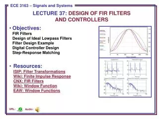
LECTURE 37: DESIGN OF FIR FILTERS AND CONTROLLERS. Objectives: FIR Filters Design of Ideal Lowpass Filters Filter Design Example Digital Controller Design Step-Response Matching

Objectives:
E N D
Presentation Transcript
LECTURE 37: DESIGN OF FIR FILTERSAND CONTROLLERS • Objectives: • FIR FiltersDesign of Ideal Lowpass FiltersFilter Design ExampleDigital Controller DesignStep-Response Matching • Resources:ISIP: Filter TransformationsWiki: Finite Impulse ResponseCNX: FIR FiltersWiki: Window FunctionEAW: Window Functions Audio: URL:
Finite Impulse Response Filters • Consider a filter with only feedforward components: • The transfer function is: • Since the impulse response of this filter, h[n], has a finite number of nonzero terms, this filter is referred to as a finite impulse response (FIR) filter. • Observe that this filter only has zeroes (the roots of H(z)).
Design of FIR Filters • The simplest method for designing an FIR filter is to construct an ideal frequency response, perform an inverse Fourier transform to obtain the impulse response, and then truncate the impulse response: • As we discussed previously, we can view this truncation operation as multiplication of a signal by a window: • Since multiplication in the time domain implies convolution in the frequency domain, the spectrum of the windowed signal is given by: • In the case of the rectangular window:
FIR Design Example • Consider the design of an ideallowpass filter. The ideal filter is noncausal for the response shown. • Introduce a phase delay which willhelp us create a causal approximation: • We can truncate the impulse response to obtain our FIR filter: • Examples of the frequency response: N = 21 N = 41 N = 21 Wc = 0.4;N = 21;m = (N-1)/2;n = 0:2*m + 10;h = Wc/pi*sinc(Wc*(n-m)/pi); w = [ones(1,N) zeros(1,length(n)-N)]; hd = h.*w;
Digital Controllers • There are many strategies for approximating an analog controllerwith a digital controller. • This is analogous to the filter designproblem, and many of the sametechniques (e.g., bilinear transform)can be applied. • This process is referred to asanalog emulation. • In this section, we will explore a technique known as step-responsematching in which we design the digital system to approximate the step response of the analog system. • The approach involves taking the inverse Laplace transform of the output, y(t), corresponding to the response of the system to a step function: • We will need to make sure the sampling interval is chosen to be small enough that the discrete system matches the analog system.
Design Example • Consider a CT system with transfer function: • The transform of the step response is: • The inverse Laplace transform is: • The discrete version is: • We can work backwards to derive the equivalent transfer function: • We can compare the frequency response of the discrete system to the analog system, and also compare impulse responses.
Design of a Feedback Controller • Consider a feedback system: • The overall transfer function is: • Using our step-response design method, with , we have: • The step response of this system can be plotted using MATLAB. • Note how the overshoot varies asa function of the sample interval. • There are a variety of ways we canapproximate an analog control systemusing a digital controller. For example,we can match the impulse responserather than the step response.
Summary • Reviewed FIR filters. • Introduced a design methodology based on truncating the impulse response of an ideal lowpass filter. • Demonstrated an application of this design approach. • Introduced a methodology for design digital controllers that can approximate an equivalent analog controller. • Demonstrated an approach involving matching the step response. • Applied this to two control examples.