Download
1 / 43
470 likes | 1.24k Views
Interrupts of 8051. Introduction 8051 Interrupt organization Processing Interrupts Program Design Using Interrupts Timer Interrupts Serial Port Interrupts External Interrupts Interrupt Timings. Interrupts.

E N D
Interrupts of 8051 • Introduction • 8051 Interrupt organization • Processing Interrupts • Program Design Using Interrupts • Timer Interrupts • Serial Port Interrupts • External Interrupts • Interrupt Timings T. L. Jong, Dept. of E.E., NTHU
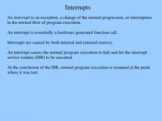
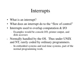
Interrupts • An interrupt is the occurrence of a condition--an event -- that cause a temporary suspension of a program while the event is serviced by another program (Interrupt Service Routine ISR or Interrupt Handler). • Interrupt-Driven System-- gives the illusion of doing many things simultaneously, quick response to events, suitable for real-time control application. • Base level--interrupted program, foreground. • Interrupt level--ISR, background. T. L. Jong, Dept. of E.E., NTHU
Time Main program (base level, foreground) Program execution without interrupts Interrupt level execution ISR ISR ISR Main Base-level execution Main Main Main Interrupt (occurs asynchronously) Return from interrupt instruction T. L. Jong, Dept. of E.E., NTHU
8051 Interrupt Organization • 5 interrupt sources: 2 external, 2 timer, a serial port • 2 programmable interrupt priority levels • fixed interrupt polling sequence • can be enabled or disabled • IE (A8H), IP (B8H) for controlling interrupts T. L. Jong, Dept. of E.E., NTHU
Enabling and Disabling Interrupts IE (Interrupt Enable Register A8H) Bit Symbol Bit Address Description (1=enable, 0=disable) IE.7 EA AFH Global enable/disable IE.6 - AEH Undefined IE.5 ET2 ADH Enable timer 2 interrupt (8052) IE.4 ES ACH Enable serial port interrupt IE.3 ET1 ABH Enable timer 1 interrupt IE.2 EX1 AAH Enable external 1 interrupt IE.1 ET0 A9H Enable timer 0 interrupt IE.0 EX0 A8H Enable external 0 interrupt • Two bits must be set to enable any interrupt: the individual enable bit and global enable bit • SETB ET1 SETB EA • MOV IE,#10001000B T. L. Jong, Dept. of E.E., NTHU
Interrupt Priority (IP, B8H) Bit Symbol Bit Address Description (1=high, 0=low priority) IP.7 - - Undefined IP.6 - - Undefined IP.5 PT2 BDH Priority for timer 2 interrupt (8052) IP.4 PS BCH Priority for serial port interrupt IP.3 PT1 BBH Priority for timer 1 interrupt IP.2 PX1 BAH Priority for external 1 interrupt IP.1 PT0 B9H Priority for timer 0 interrupt IP.0 PX0 B8H Priority for external 0 interrupt • 0= lower priority, 1= higher priority, reset IP=00H • Lower priority ISR can be interrupted by a high priority interrupt. • A high priority ISR can not be interrupted. T. L. Jong, Dept. of E.E., NTHU
Interrupt Flag Bits Interrupt Flag SFR Register & Bit Position ------------------------------------------------------------------------------ External 0 IE0 TCON.1 External 1 IE1 TCON.3 Timer 1 TF1 TCON.7 Timer 0 TF0 TCON.5 Serial port TI SCON.1 Serial Port RI SCON.0 Timer 2 TF2 T2CON.7 (8052) Timer 2 EXF2 T2CON.6 (8052) • The state of all interrupt sources is available through the respective flag bits in the SFRs. • If any interrupt is disabled, an interrupt does not occur, but software can still test the interrupt flag. T. L. Jong, Dept. of E.E., NTHU
Polling Sequence • If two interrupts of the same priority occur simultaneously, a fixed polling sequence determines which is serviced first. • The polling sequence is External 0 > Timer 0 > External 1 > Timer 1 > Serial Port > Timer 2 T. L. Jong, Dept. of E.E., NTHU
High priority interrupt IP register IE register 1 IE0 INT0 IT0 0 Low priority interrupt TF0 1 IE1 IT1 INT1 Interrupt polling sequence 0 TF1 RI TI TF2 EXF2 Interrupt enables Accent interrupt Global Enable T. L. Jong, Dept. of E.E., NTHU
Processing Interrupts • When an interrupt occurs and is accepted by the CPU, the main program is interrupted. The following actions occur: • The current instruction completes execution. • The PC is saved on the stack. • The current interrupt status is saved internally. • Interrupts are blocked at the level of the interrupt. • The PC is loaded with the vector address of the ISR • The ISR executes. • The ISR finishes with an RETI instruction, which retrieves the old value of PC from the stack and restores the old interrupt status. Execution of the main program continues where it left off. T. L. Jong, Dept. of E.E., NTHU
Interrupt Vectors • Interrupt vector = the address of the start of the ISR. • When vectoring to an interrupt, the flag causing the interrupt is automatically cleared by hardware. The exception is RI/TI and TF2/EXF2 which should be determined and cleared by software. Interrupt Flag Vector Address System Reset RST 0000H (LJMP 0030H) External 0 IE0 0003H Timer 0 TF0 000BH External 1 IE1 0013H Timer 1 TF1 001BH Serial Port RI or TI 0023H Timer 2 TF2 or EXF2 002BH T. L. Jong, Dept. of E.E., NTHU
Program Design Using Interrupts • I/O event handling: • Polling: main program keeps checking the flag, waiting for the occurrence of the event. Inefficient in some cases. • Interrupt-driven: CPU can handle other things without wasting time waiting for the event. Efficient, prompt if ISR is not so complex. Suitable for control application. • I/O processor: dedicated processor to handle most of the I/O job without CPU intervention. Best but most expensive. T. L. Jong, Dept. of E.E., NTHU
8051 Program Design Using Interrupt ORG 0000H ;reset entry point LJMP Main ;takes up 3 bytes ORG 0003H ;/INT0 ISR entry point . ;8 bytes for IE0 ISR or . ; jump out to larger IE0 ISR ORG 000BH ;Timer 0 ISR entry point . . ORG 0030H ;main program entry point Main: . . . T. L. Jong, Dept. of E.E., NTHU
Small Interrupt Service Routine • 8 bytes for each interrupt vector. Small ISR utilizes the space. • For example: (assume only T0ISR is needed in the case) ORG 0000H LJMP MAIN ORG 000BH T0ISR: . . RETI MAIN: . ;only T0ISR T. L. Jong, Dept. of E.E., NTHU
Large Interrupt Service Routine • 8 bytes not enough. Use LJMP to large ISR ORG 0000H LJMP MAIN ORG 000BH ; T0 ISR entry point LJMP T0ISR ORG 0030H ;above int vectors MAIN: . . T0ISR: . ; Timer 0 ISR . RETI ;return to main T. L. Jong, Dept. of E.E., NTHU
A 10-KHz Square Wave on P1.0 Using Timer Interrupts ORG 0 ;reset entry point LJMP Main ORG 000BH ;T0 interrupt vector T0ISR: CPL P1.0 ;toggle port bit RETI ORG 0030H Main: MOV TMOD,#02H ;T0 MODE 2 MOV TH0,#-50 ;50 mS DELAY SETB TR0 ;START TIMER 0 MOV IE,#82H ;ENABLE T0 INT SJMP $ ;DO NOTHING T. L. Jong, Dept. of E.E., NTHU
Two 7-KHz & 500-Hz Square Waves Using Interrupts ORG 0 ;reset entry point LJMP Main ORG 000BH ;T0 interrupt vector LJMP T0ISR ORG 001BH ;T1 vector LJMP T1ISR ORG 0030H ;main starts here Main: MOV TMOD,#12H ;T0 mode 2, T1 mode 1 MOV TH0,#-71 ;7-kHz using T0 SETB TR0 ;START TIMER 0 SETB TF1 ;force T1 int MOV IE,#8AH ;ENABLE T0,T1 INT SJMP $ ;DO NOTHING T. L. Jong, Dept. of E.E., NTHU
Two 7-KHz & 500-Hz Square Waves Using Interrupts (cont.) T0ISR: CPL P1.7 ;7-kHz on P1.7 RETI T1ISR: CLR TR1 ;stop T1 MOV TH1,#HIGH(-1000) MOV TL1,#LOW(-1000) ;1 ms for T1 SETB TR1 ;START TIMER 1 CPL P1.6 ;500-Hz on P1.6 RETI T. L. Jong, Dept. of E.E., NTHU
Serial Port Interrupts • SPISR must check RI or TI and clears it. • TI occurs at the end of the 8th bit time in mode 0 or at the beginning of stop bit in the other modes. Must be cleared by software. • RI occurs at the end of the 8th bit time in mode 0 or half way through the stop bit in other modes when SM2 =0. If SM2 = 1, RI = RB8 in mode 2,3 and RI = 1 only if valid stop bit is received in mode 1. T. L. Jong, Dept. of E.E., NTHU
Output ACSII Code Set Using Interrupt (1) ;dump ASCII codes to serial port ORG 0 LJMP Main ORG 0023H ;serial port vector LJMP SPISR ORG 0030H ;main entry point Main: MOV TMOD,#20H ;Timer 1 mode 2 MOV TH1,#-26 ;use 1200 baud SETB TR1 ;start T1 MOV SCON,#42H ;mode1, set TI to force first ;interrupt; send 1st char. MOV A,#20H ;send ASCII space first MOV IE,#90H ;enable SP interrupt SJMP $ ;do nothing T. L. Jong, Dept. of E.E., NTHU
Output ACSII Code Set Using Interrupt (2) SPISR: CJNE A,#7FH,Skip ;if ASCII code = 7FH MOV A,#20H ;wrap back to 20H Skip: MOV SBUF,A ;start to transmit INC A CLR TI ;clear TI flag RETI The CPU speed is much higher than 1200 baud serial transmission. Therefore, SJMP executes a very large percentage of the time. Time for one char = (1/1200 baud)(8+1+1) = 8333.3 mS compared to 1 mS machine cycle! We could replace SJMP instruction with other useful instructions doing other things. T. L. Jong, Dept. of E.E., NTHU
#include “io51.h” char *ptr; void InitialUART(int BaudRate) /*Max baudrate = 9600*/ { SCON = 0x52; TMOD = 0x21; TH1 = 256-(28800/BaudRate); /*11.059M/384=28800*/ TR1 = 1; } static const char msg1[]=“UART interrupt message!!”; void main(void) { InitialUART(9600); EA = 1; ptr = msg1; ES = 1; while(1); /*wait for SP interrupt*/ } T. L. Jong, Dept. of E.E., NTHU
interrupt [0x23] void SCON_int(void) /*Serial port ISR*/ { if(RI==1)RI=0; /* we did nothing in this program for RxD */ if(TI==1) { TI=0; if(*ptr!=‘\0’) /*string ends with ‘\0’ character*/ { SBUF=*ptr; ++ptr; } else { ES=0; /*complete a string tx, clear ES and let*/ TI=1; /*main program decide next move */ } } } T. L. Jong, Dept. of E.E., NTHU
External Interrupts • /INT0 (P3.2 or pin12) and /INT1 (P3.3 or pin 13) produce external interrupt in flag IE0 and IE1 (in TCON) in S5P2. • /INT0 and /INT1 are sampled once each machine cycle (S5P2) and polled in the next machine cycle. An input should be held for at least 12 clock cycles to ensure proper sampling. • Low-level trigger (IT0 or IT1 =0): interrupt when /INT0 or /INT1 = 0 • Negative edge trigger (IT0 or IT1 = 1): interrupt if sense high on /INT0 or /INT1 in one machine cycle and low in next machine cycle. • IE0 and IE1 are automatically cleared when CPU is vectored to the ISR. T. L. Jong, Dept. of E.E., NTHU
External Interrupts • If the external interrupt is low-level triggered (IT0 or IT1 =0), the external source must hold the request active until the requested interrupt is actually generated. • Then it must deactivate the request before the ISR is completed, or another interrupt will be generated. • Usually, an action taken in the ISR causes the requesting source to return the interrupting signal to the inactive state. T. L. Jong, Dept. of E.E., NTHU
Furnace Controller 8051 HOT = 0 if T > 21C INT0 1 = solenoid engaged (furnace on) if T < 19C 0 = solenoid disengaged (furnace off) if T > 21C P1.7 COLD = 0 if T < 19C INT1 T = 21C T = 20C T = 19C HOT COLD P1.7 T. L. Jong, Dept. of E.E., NTHU
Furnace Controller ORG 0 LJMP Main EX0ISR: CLR P1.7 ;turn furnace off RETI ORG 13H EX1ISR: SETB P1.7 ;turn furnace on RETI ORG 0030H Main: MOV IE,#85H ;enable ext int SETB IT0 ;negative edge trigger SETB IT1 SETB P1.7 ;turn furnace on first JB P3.2,Skip ;if T>21? CLR P1.7 ;yes, turn furnace off Skip: SJMP $ ;do nothing T. L. Jong, Dept. of E.E., NTHU
8051 74LS04 INT0 P1.7 Door opens Intrusion Warning System 1 sec P1.7 P1.7 400Hz 1.25 ms 2.5 ms T. L. Jong, Dept. of E.E., NTHU
Intrusion Warning System ORG 0 LJMP Main LJMP EX0ISR ORG 0BH LJMP T0ISR ;use T0 and R7=20 time 1 s ORG 1BH LJMP T1ISR ;use T1 to sound alarm Main: SETB IT0 ;negative edge trigger MOV TMOD,#11H ;16-bit timer MOV IE,#81H ;enable EX0 only Skip: SJMP $ ;relax & wait for intrusion T. L. Jong, Dept. of E.E., NTHU
Intrusion Warning System EX0ISR: MOV R7,#20 ;20x50000 ms = 1 s SETB TF0 ;force T0 ISR SETB TF1 ;force T1 ISR SETB ET0 ;enable T0 int SETB ET1 ;enable T1 int RETI T0ISR: CLR TR0 ;stop T0 DJNZ R7,SKIP ;if not 20th time, exit CLR ET0 ;if 20th, disable itself CLR ET1 ;and tone LJMP EXIT SKIP: MOV TH0,#HIGH(-50000) ;reload 0.05 s MOV TL0,#LOW(-50000) ;delay SETB TR0 ;turn on T0 again EXIT: RETI T. L. Jong, Dept. of E.E., NTHU
Intrusion Warning System ; T1ISR: CLR TR1 ;stop T1 MOV TH1,#HIGH(-1250) ;count for 400 Hz MOV TL1,#LOW(-1250) ;tone CPL P1.7 ;music maestro SETB TR1 ; RETI T. L. Jong, Dept. of E.E., NTHU
Interrupt Timing 1 • Since the external interrupt pins are sampled once each machine cycle, an input high or low should hold for at least 12 oscillator periods to ensure sampling. • If the external interrupt is transition-activated, the external source has to hold the request pin high for at least one cycle, and then hold it low for at least one cycle. This is done to ensure that the transition is seen so that interrupt request flag IEx will be set. • IEx will be automatically cleared by the CPU when the service routine is called. T. L. Jong, Dept. of E.E., NTHU
Interrupt Timing 2 • If the external interrupt is level-activated, the external source has to hold the request active until the requested interrupt is actually generated. Then it has to deactivate the request before the interrupt service routine is completed, or else another interrupt will be generated. T. L. Jong, Dept. of E.E., NTHU
Interrupt Timing 3 • Response Time The /INT0 and /INT1 levels are inverted and latched into IE0 and IE1 at S5P2 of every machine cycle. The values are not actually polled by the circuitry until the next machine cycle. • If a request is active and conditions are right for it to be acknowledged, a hardware subroutine call to the requested service routine will be the next instruction to be executed. The call itself takes two cycles. Thus, a minimum of three complete machine cycles elapse between activation of an external interrupt request and the beginning of execution of the first instruction of the service routine. T. L. Jong, Dept. of E.E., NTHU
Interrupt Timing 4 • A longer response time would result if the request is blocked by one of the 3 previously listed conditions. 1. An interrupt of equal or higher priority level is already in progress. 2. The current (polling) cycle is not the final cycle in the execution of the instruction in progress. (ensure completion) 3. The instruction in progress is RETI or any write to the IE or IP registers. (one more instruction will be executed) • If an interrupt of equal or higher priority level is already in progress, the additional wait time obviously depends on the nature of the other interrupt’s service routine. T. L. Jong, Dept. of E.E., NTHU
Interrupt Timing 5 • If the instruction in progress is not in its final cycle, the additional wait time cannot be more than 3 cycles, since the longest instructions (MUL and DIV) are only 4 cycles long, and if the instruction in progress is RETI or an access to IE or IP, the additional wait time cannot be more than 5 cycles (a maximum of one more cycle to complete the instruction in progress, plus 4 cycles to complete the next instruction if the instruction is MUL or DIV). • Thus, in a single-interrupt system, the response time is always more than 3 cycles and less than 9 cycles. T. L. Jong, Dept. of E.E., NTHU
Interrupt Response Timing Diagram: Fastest T. L. Jong, Dept. of E.E., NTHU
Interrupt Response Timing Diagram: Longest Level 0 ISR Main program Level 0 ISR RETI MUL AB Save PC ISR 9 cycles Level 1 interrupt occurs here (missed last chance before RETI instruction) T. L. Jong, Dept. of E.E., NTHU
Interrupt Timing 6 Single-Step Operation • The 80C51 interrupt structure allows single-stepexecution with very little software overhead. As previously noted, an interrupt request will not be responded to while an interrupt of equal priority level is still in progress, nor will it be responded to after RETI until at least one other instruction has been executed. Thus, once an interrupt routine has been entered, it cannot be re-entered until at least one instruction of the interrupted program is executed. • One way to use this feature for single-step operation is to program one of the external interrupts (e.g., /INT0) to be level-activated. T. L. Jong, Dept. of E.E., NTHU
Interrupt Timing 7 • The service routine for the interrupt will terminate with the following code: JNB P3.2,$ ;Wait Till /INT0 Goes High JB P3.2,$ ;Wait Till /INT0 Goes Low RETI ;Go Back and Execute One Instruction • Now if the /INT0 pin, which is also the P3.2 pin, is held normally low, the CPU will go right into the External Interrupt 0 routine and stay there until /INT0 is pulsed (from low to high to low). Then it will execute RETI, go back to the task program, execute one instruction, and immediately re-enter the External Interrupt 0 routine to await the next pulsing of P3.2. One step of the task program is executed each time P3.2 is pulsed. T. L. Jong, Dept. of E.E., NTHU
Interrupt Timing 8 Reset • The reset input is the RST pin, which is the input to a Schmitt Trigger. • A reset is accomplished by holding the RST pin high for at least two machine cycles (24 oscillator periods), while the oscillator is running. The CPU responds by generating an internal reset. • The external reset signal is asynchronous to the internal clock. The RST pin is sampled during State 5 Phase 2 of every machine cycle. The port pins will maintain their current activities for 19 oscillator periods after a logic 1 has been sampled at the RST pin; that is, for 19 to 31 oscillator periods after the external reset signal has been applied to the RST pin. T. L. Jong, Dept. of E.E., NTHU
Reset Timing T. L. Jong, Dept. of E.E., NTHU
Interrupt Timing 9 • The internal reset algorithm writes 0s to all the SFRs except the port latches, the Stack Pointer, and SBUF. • The port latches are initialized to FFH (input mode), the Stack Pointer to 07H, and SBUF is indeterminate. • The internal RAM is not affected by reset. On power up the RAM content is indeterminate. T. L. Jong, Dept. of E.E., NTHU