Laboratory 2
Laboratory 2. A self balancing platform. Objectives. 1. Objectives To lean how to interface a direct current (DC) output sensor to an microcontroller To learn how to implement a Proportional–Integral–Derivative PID feed back control system. 2. Aim


Laboratory 2
E N D
Presentation Transcript
Laboratory 2 A self balancing platform Lab2: A self balancing platform v.9b
Objectives • 1. Objectives • To lean how to interface a direct current (DC) output sensor to an microcontroller • To learn how to implement a Proportional–Integral–Derivative PID feed back control system. • 2. Aim • To develop a self-balancing platform using an embedded system. • Reference: http://www.cse.cuhk.edu.hk/%7Ekhwong/ceg3480/PID_DC_motor_Control08.ppt Lab2: A self balancing platform v.9b
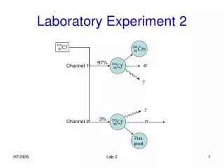
control method:PID (proportional-integral-derivative) control Required position=0 Integral control I* (deltal) dt error term e=0-tmpl =deltal 0 PWM generator Proportional control =P*(deltal) + - sum tmpl Left_pwm Derivative control D*d(deltal)/dt ; Position Sensor (tmpl) Lab2: A self balancing platform v.9b
The experimental setup video Lab2: A self balancing platform v.9b
Fig. 1b.Block Diagram of the Self-balancing platform Lab2: A self balancing platform v.9b
Fig. 2 Two channels DC amplifier circuit Lab2: A self balancing platform v.9b
Fig. 3 (a) Top View of the Accelerometer , (b) the sensor attached to the bottom of the platform x-axis y-axis In the arm mcu we set 15000 = read_sensor(1.5V); Lab2: A self balancing platform v.9b
Special techniques • MIDL is the mid set point value for X-axis • Use integer “int” to simulate floating point • Multiply the value by x and divide it by x afterwards, (e.g. x=200 in our example) • tmpl is the tilt position measurement • e=deltal = (tmpl - (MIDL+200)) / 200; • Derivative is d[e(t)] / dt = e (current ) – e (previous) • diffl = deltal – lastl; • Integration is e dt = e (current) + e (previous) • accul += deltal/200; //arbitrary set to divide by 200, Dead-band (see next page) Lab2: A self balancing platform v.9b
Dead band • Dead-band : A Dead-band (sometimes called a neutral zone) is an area of a signalrange or band where no action occurs : only enable motor when tile angle outside +/- degrees (=0.1 degrees). http://en.wikipedia.org/wiki/Dead-band Dead-band Lab2: A self balancing platform v.9b
Algorithm of left motor (core loop in timer IRQ_exception) 500Hz • void __irq IRQ_Exception() • { • tmpl = read_sensor(0); // read X-axis value • //putint(tmpl); // display on terminal • // print("; "); • if (tmpl>=(MIDL+200)) { // if X-axis value >= setpoint plus 200 • deltal = (tmpl - (MIDL+200))/200; // calculate the error and normalize it • diffl = deltal-lastl; // caculate the different between current and last error • if(diffl<maxdiff) { // ignore if the error different > max. difference • // this prevent the noise due to undesired movement of accelerometer • lastl = deltal; // save error as the last error • leftPWM = leftPWM - (P*deltal - I*accul + D*diffl); // update the left PWM value by PID • if (leftPWM<MINOUTPUT) leftPWM = MINOUTPUT; // limit the PWM value to its minimum • if(accul<maxaccu) accul += deltal/200; // ensure the integral not exceed the maximum • PWMMR2=leftPWM; // set the left PWM output • PWMLER = 0x24; //enable match 2,5 latch to effective • } • } • else if (tmpl<=(MIDL-200)) { // if X-axis value <= setpoint plus 200 • deltal = ((MIDL-200) - tmpl)/200; // calculate the error and normalize it • diffl = deltal- lastl; // caculate the different between current and last error • if(diffl<maxdiff) { // ignore if the error different > max. difference • // this prevent the noise due to undesired movement of accelerometer • lastl = deltal; // save error to the last error • leftPWM = leftPWM + P*deltal + I*accul + D*diffl; // update the left PWM value by PID • if (leftPWM>MAXOUTPUT) leftPWM = MAXOUTPUT; // limit the PWM value to its maximum • if(accul>0) accul -= deltal/100; // ensure the integral not less than zero • PWMMR2=leftPWM; // set the left PWM output • PWMLER = 0x24; //enable match 2,5 latch to effective • } • } • //////////////////////////////////////////////////// Lab2: A self balancing platform v.9b
if (tmpl>=(MIDL+200))Tile position > degrees (outside dead band) • void __irq IRQ_Exception() //running at 500Hz, set by timer • { tmpl = read_sensor(0); // read X-axis value //putint(tmpl); • if (tmpl>=(MIDL+200)) {// if X-axis value >= setpoint plus 200 • deltal = (tmpl - (MIDL+200))/200; // cal.error and normalize it • diffl = deltal-lastl; // cal. different between current and last error • if(diffl<maxdiff) // ignore if the error different > max. difference • {//prevents noise from undesired accelerometer movement lastl = deltal; // save error as the last error • leftPWM = leftPWM - (P*deltal - I*accul +D*diffl);//updatePWM • if (leftPWM<MINOUTPUT) • leftPWM = MINOUTPUT;// limit PWM to its min. • if(accul<maxaccu) //make sure accul cannot grow too big • accul += deltal/200; • // ensure integral< maximum • PWMMR2=leftPWM;// set the left PWM output • PWMLER = 0x24;//enable match 2,5 latch to effective • } • } Lab2: A self balancing platform v.9b
Else of if (tmpl>=(MIDL+200))Tile position <= degrees (outside dead band) • else if (tmpl<=(MIDL-200)) • { Similar but the rotation is reversed • }//////////////////////////////////////////////////// Lab2: A self balancing platform v.9b
Question • Is the output voltage changes linearly with the tilt angle? • What is the effect on the performance of the system when the sampling frequency is 100Hz? • The deadband in sensor reading is +/-200. Estimate the deadband in degrees of our system. • What is the effect on the performance of the system when the sampling frequency is 1000Hz? Explain your observation. Lab2: A self balancing platform v.9b
Conclusion • Studied how to interface direct currents sensor to a embedded system • Studied how to build and tune a PID control system Lab2: A self balancing platform v.9b