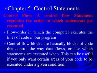
Download

1 / 25
250 likes | 423 Views
External memory. Microprocessor. Output port/buffer. Control code in the memory (The flow chart of the control code shown in Fig.-8.2). W O R K S P A C E. Temporary memory-3. Temporary memory-1. Temporary memory-2. Limit switch-1. Pyroelectric transducer. Limit

E N D
External memory Microprocessor Output port/buffer Control code in the memory (The flow chart of the control code shown in Fig.-8.2) W O R K S P A C E Temporary memory-3 Temporary memory-1 Temporary memory-2 Limit switch-1 Pyroelectric transducer Limit switch-2 Input port/buffer Input port/buffer Input port/buffer Analog to digital converter Analog to digital converter Analog to digital converter Motor Digital to analog converter Microprocessor/microcontroller is a digital device composed of millio-ns of transis-tors within a single wafer or single sem-iconductor piece. It is called a Very Large Scale Integ-rated (VLSI) chip that represent the heart of control applications. The microprocessor and microcontroller based control solution facilitate higher integration providing incredible performance. They take less space and also consume low power.
Start Is temporary memory-1 is full? No Yes Turn on the motor Reset the temporary memory -1 Is temporary memory-2 is full? No Yes Wait for 5 seconds Rotate the motor in reverse direction Stop the motor Reset temporary memory-2 No Is temporary memory-3 is full? Yes Stop the motor Reset the temporary memory-3 Control code of a typical automatic door (in flow chart form). The control system automatically opens the door when a person approaches, and automatically closes. An electric motor based actuator fitted with other auxiliary electronics and mechanical components, is responsible for sliding the door on the rail.
Memory device Its address D E C O D E R Data lines (bi-directional) 0000 0001 0002 0003 0004 0005 0006 0007 03FA Address lines/pins (Unidirectional) 03FB 03FC 03FD 03FE 03FF A memory is a physical device where program, data etc. are stored. The contains many memory locations. Each location is defined in terms of an address, which is a unique number within a particular microprocessor-based control application. The figure illustrates a memory device whose address space is 0000 to 03FF. The length of the address space of this chip is 1 K bytes.
Memory Holding the program Address 2000 Address path 2001 2002 2003 2004 2005 2006 Microprocessor 2007 2008 Data or Instruction path 2009 200A 200B 200C 200D 200E 200F Memory Select Signal A program is a logical sequence of instructions that directs the microprocessor to perform a desired task. Once a program is developed, it is stored in the memory sequentially. In a typical example, if the program resides in the memory locations 2000H to 200FH, then the microprocessor addresses the locations and fetches program codes from the memory, one by one.
8-bit Temporary registers 16-bit Temporary registers The CPU require some temporary storage cells so that intermediate data can be stored temporarily, either for data transaction or for latter use. The temporary storage cells are called temporary registers.
Input Buffer 10011100 Memory holding a data byte 1 0 0 1 1 1 0 0 1 0 0 1 1 1 0 0 Data Register Data Register is a special register, which holds data when they are fetched from the memory or input devices
Instruction OPCODE = 59 D E C O D E R FD 0000 Instruction register 59 3C 0001 59 0002 76 2003 Address Instruction decoder Memory Control signals Address=0002 Instruction Register (IR) only accommodates instructions. The user written program (OPCODE) flows from the memory into the microprocessor in sequence. The OPCODE is placed in the IR. In this typical example, the OPCODE 59 (‘01011001’) located at memory location 0002H has been fetched and placed in the IR of the microprocessor.
External Input devices Input Buffer Internal Registers Output Buffer To External Output devices Buffers are registers, which hold data or address those come in and go out of the microprocessor. The difference between the buffer and other registers in the microprocessor is that the data or address is first entered into the input buffer and then transferred to a specified register. Similarly, the data are sent out from any register(s) to the outside world via output buffer. The buffers are apparently some sorts of I/O (Input/Output) ports.
Program Counter (PC) is a register that holds the addr-ess of the next instruction. At the end of the execution of the current instruct-ion, the content 2000 2001 2002 D E C O D E R 2003 2004 Program Counter 2005 2006 2007 0 0 1 0 0 0 0 0 0 0 1 0 0 0 0 0 0 0 0 0 1 1 0 0 0 0 0 0 1 1 0 0 2008 2009 200A Memory address register 200B 200C 200D 200E 200F Address Decoder selects location 200C Memory Holding the program of the PC (the next address) is transferred to the memory and decoded in order to get the next item of the executable code. The next item could be a data or an instruction. The content of the Program Counter is placed on the Memory Address Register (MAR) before the address is transferred to the decoder of the memory device.
Sigh Bit C = Carry Bit P = Parity Bit Z = Zero Bit S = Sign Bit X = This Bit not in use (don’t care) Flag Register Flag Bits (a) (b) Flag Register Accumulator (ACC) C P Z S X X X X 0 0 0 0 0 0 0 0 0 1 1 0 X X X X The flag register in the microprocessor is a special purpose register in which the individual bit values represents the standing of a result byte. The flag bits are automatically modified in accordance with the result and the type of operation performed.
Crystal frequency Microprocessor operates at this frequency State The microprocessor processes data at a rate, which is determined by the clock signal (crystal output) it has been provided with. The time required to complete a read (fetch) and write cycle is measured in terms of state. The state is related to the clock frequency of the microprocessor and it is half of the crystal frequency.
Internal bus Bi-directional bus External A typical unit within the microprocessor Another Unit Unidirectional Bus Bus can be used in multiplexed mode Registers OPCODE, operands and address bytes are transferred through bus. A bus is a transmitting media consisting of group of lines. The number of lines are usually 8, 16, 32, etc. They connect each and every unit within the microprocessor. Some buses are bi-directional and some are unidirectional, meaning the bi-directional buses transfers data in both directions, where as unidirectional buses carries data in only one direction. Buses, which carry address and data are called address-bus and data-bus, respectively. They may be external or internal. Some busses are used in multiplexed mode.
OPCODE From Memory Instruction Register Instruction decoder (Microcode Engine) Control Signals other units of the microprocessor The OPCODE is decoded to generate control signals for ‘what to do next’. As a result a unique set of control signal is generated. If the instruction is for addition, then addition related control signals are produced. If the OPCODE is a comparison instruction, then comparison related control signals are produced.
Interrupt pin-n Interrupt pin-2 Analog to Digital Converter Interrupt acknowledge pin of the Microprocessor SENSOR Interrupt line Interrupt pin of the Microprocessor Interrupt pin of A/D converter In a typical microprocessor-based control implementation usually the external input devices such as sensors, A/D converters, Input ports, Programmable Interrupt Controller (PIC), Direct Memory Access Controller (DMAC), etc. are interfaced with the microprocessor through some special lines called interrupt lines or interrupt pins, and these lines are input lines. The data transformation is called interrupt-driven data transformation.
BEFORE INTERRRUPT A Register PC SP 200C 8D 3000 2000 5000 5001 2001 5002 2002 5003 2003 2004 5004 2005 300A 5005 D E C O D E R 2006 3009 5006 3008 2007 5007 5008 2008 3007 D E C O D E R 2009 5009 3006 500A 200A 3005 D E C O D E R 3004 500B 200B 500C 200C 3003 500D 3002 200D 500E 200E 3001 200F 3000 500F Address Stack Address Interrupt Subroutine Address Memory Holding the Main program Stack is a user defined memory space, which includes many locations within the memory space of the micropr-ocessor. These memory locati- Before interruption ons are special in the sense that when interrupts occur, the micr-oprocessor stores the current content of the various registers and flags in the stack in order to attend the interrupt.
AFTER INTERRRUPT A Register PC SP 5000 3002 2000 5000 2001 5001 2002 5002 2003 5003 5004 2004 2005 5005 300A D E C O D E R 5006 2006 3009 5007 3008 2007 5008 2008 3007 D E C O D E R 5009 2009 3006 500A 200A 3005 D E C O D E R 3004 200B 500B 500C 3003 200C 500D 200D 3002 500E 200E 3001 200F 500F 3000 8D 20 0C Address Stack Address Interrupt Subroutine Address Memory Holding the Main program After interruption
To Memory and I/O Data path Address path Flag bits Instruction Register (IR) Data Register (DR) Bi-directional Bus Microcode Engine Register set Stack Pointer Control signals Program Counter Bus Memory Address Register (MAR) ALU Unidirectional Bus Accumulator Address path To Memory and Output Minimum configuration of a typical microprocessor
Intel’s 8085A Microprocessor Architecture TRAP RST 7.5 RST 6.5 RST 5.5 INTRA INTR SID SOD Interrupt Control Unit Serial I/O Control Unit Temporary Register Accumulator (ACC) Instruction register C B E D L H PC ALU Instruction Decoder SP Incrementer/Decrementer Timing and Control unit WR IO/M RD Address Buffer Address/Data Buffer RESET OUT RESET IN Clock out ALE HLD READY HLDA
State-1 (send address) State-2 (Read) State-3 (Fetch) Fetch cycle Data are transferred from and into the microprocessor through 8 lines, i.e., through pins. Thus are used in multiplexed mode; they carry both data and address. Within a fetch cycle the address is sent during the first state of the cycle. During the second state the content of the specified memory location is read and during the third state the content is transferred into the microprocessor through the same lines/pins.
ALU Register set Buffers Instruction decoder Control Unit PC, SP Interrupt controller SID/SOD Unit Busses CPU CPU CPU (a) (b) (c) • Microprocessor • with one CPU. • (b) with two CPUs. • (c) with three CPUs The microprocessor or microcontroller might contain one or more CPUs as
ALU Register set Buffers Instruction decoder Control Unit PC, SP Interrupt controller SID/SOD Unit Busses A/D converter Memory controller Programmable timer Pulse width modulator Digital I/O Phase locked loop Memory controller EPROM, ROM CPU (a) (b) CPU CPU As far as architecture is concerned, microcontroller, unlike microprocessor, contains many additional peripheral units along with the common functional units. The functional units are arithmetic and logic unit, Register sets, Program Counter, Stack Pointer, Control Circuitry, etc. These common and basic functional units are required to interpret and execute instructions or program. The additional units are called peripheral units. These include A/D converter, Programmable timer, Pulse width Modulator, Phase locked loop, Memory controller, EPROM, ROM , etc.
Microprocessor Microcontroller Signal conditioning circuits and interfacing (Peripheral Units) PLANT PLANT = ACRUATOR (motor) = ACRUATOR (motor) = SENSORS (Encoder, switch) = SENSORS (Encoder, switch) In microprocessor-based solution the external units have to be integrated or interfaced, requiring additional task and connectivity. On the other hand microcontroller-based control design do not require additional peripheral units since they have been built into the processor chip. They are more reliable, since little or fewer additional connections and interfacings are required thus reducing part size and enhancing real-time performance and efficiency.
V (Ref) ANGND Reference frequency Clock OTPROM 16K – KC 32K - KD A/D Converter Register file 512 bytes in KC 1024 bytes in KD RALU Interrupt Controller PTS S/H Microcode engine Memory Controller Control Signals Port 3 Port 4 HOLD HOLDA BREQ PWM 1 PWM 2 Queue MUX Address Data Bus T2CAPT Timer 2 Timer 1 Watchdog Timer Serial Port Boud Rate Generator Port 1 Port 0 PWM Port 2 Multiplexure High Speed I/O A/D Port 0 HIS HSO Port 1 Port 2 Architecture of Intel’s 8CX196KC/KD Microcontroller
RALU Memory Controller Master PC with Incrementer 6-bit Loop Counter With Decrementer BUS CONTROLLER CPU Memory Bus Upper word register With Shifter 2nd Operand Register Register File Lower word Register With Shifter Constants Register RAM Queue Slave PC Address Register Data Register Program Status Word (PSW) 3-bit Select Register Instruction Register A B ALU SFR PSW control Microcode Engine Interrupt Controller CPU Control And status signals 16 MUX MUX CPU BUSSES 8 Core Units of the 8CX196KC/KD Microcontroller
CPU Input Module Relays Output Module Relays Output (ON/OFF) Input Memory The building blocks of a typical PLC Programmable Logic Controllers (PLC) have long been used in the industrial automation platform. The primary reason for designing such a device was to facilitate communication capability and to replace the sluggish relay based control systems. The PLCs have been applied for factory automation, machine control, process control, instrumentation, data acquisition and control and many manufacturing systems