Download
1 / 1
10 likes | 202 Views
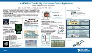
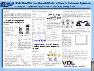
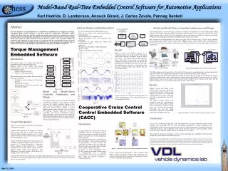
Model-Based Real-Time Embedded Control Software for Automotive Applications. Figure 3. Decomposition of the vehicle control system. Figure 2. Vehicle model. We can concentrate on editing Simulink model . Figure 4. Results of CACC cruise control run, on test track. Auto- Code by

E N D
Model-Based Real-Time Embedded Control Software for Automotive Applications Figure 3. Decomposition of the vehicle control system Figure 2. Vehicle model We can concentrate on editing Simulink model Figure 4. Results of CACC cruise control run, on test track Auto- Code by ‘Target-Link’ C code Simulink Model Execution Exec. file MPC555 Microcontroller Compiled by ‘Tornado’ Figure 1. Intelligent cruise control software development process. Karl Hedrick, D. Lamberson, Anouck Girard, J. Carlos Zavala, Pannag Sanketi Abstract The development and implementation of model-driven architectures for integrated real-time, embedded, hybrid control software is described using two applications: automotive engine control (in which electronic throttle control and air/fuel ratio control are integrated to form a unifying torque control strategy) and Adaptive Cruise Control (ACC), in which a forward looking range sensor (radar or Lidar, usually) is used to follow a vehicle . The associated models are presented and simulated and the outcome is compared with the experimental results obtained using a suitable testbed. We emphasize the integration of software along the development process and point out issues found during the implementation on a particular hardware platform. Software Design and Implementation Model and Model-Driven Controller Architecture and Design The vehicle model, as shown in figure 2 used for controller development is an eleven-state model, which includes vehicle state dynamics, throttle and brake system dynamics, and a two-state model for the spark- ignition engine. We consider only the longitudinal control of passenger vehicles (no automatic steering). Vehicles may be heterogeneous, that is, of different types, makes and models. • We used a model-based approach founded on: (fig 4). • The use of a model as the source from design to implementation. • Use of analysis and simulation tools, • Rapid prototyping tools and automatic code generators. • Connection of tools along the design and implementation chain. • Advantages: • Reduction of possibility of manual mistakes. • Reuse of code. • Higher Confidence in source models. The controller was split hierarchically between an upper and a lower level (fig. 3). Upper level controller has several modes, namely cruise control (CC), adaptive cruise control (ACC) and coordinated ACC (CACC). The lower level controller switches between throttle and brake actuation depending on the desired acceleration. Figure 4 Torque Management Embedded Software Results Figure 5 shows the throttle response to a sinusoidal input of the pedal position. The engine speed is also shown for reference. Figure 6, shows the results of the factory AFR controller Figure 7 shows the results of this same test using the controller presented in this poster. As shown, the Berkeley fuel controller forces the air to fuel ratio (the lambda sensor output) to cycle between lean and rich operation much more quickly that the production control. • Introduction • The current practice is to design and implement embedded systems separately (figure 1a): • Changes made to the control code during implementation code are not reflected back into the simulation model: • Hand Coding and rework. • Model not reflecting updates. • The model-based process ( figure 1b) we present in this poster represents: • Integrating various phases of the design process. • Traceability of errors. • Minimization of the cost associated with fixing the problems Figure 5 The TEJA-generated software for CC, ACC and CACC was run on experimental test vehicles operated by California PATH. The experimental vehicles are 1996 and 1997 model-year Buick LeSabres. They are equipped with throttle, brake and steering actuating systems, as well as with numerous sensors, including accelerometers, wheel speed sensors, engine speed and manifold pressure sensors, as well as magnetometers that are used as part of the lateral control. In addition, for our project, both radars and the lidar described above were mounted to the front bumper of the vehicles. Results Figure 4 shows the results of the CACC cruise control run. The Green line indicates velocity of lead car, red velocity of follower car, blue lines indicate relative velocity as obtained from the communications and radar filtering. The vehicle speeds match well, especially when the discontinuous nature of the speed profile is taken into consideration. A constant range policy was used for this particular low-speed test and the range between the vehicles was maintained at 15 meters throughout the test. Figure 6 Figure 1a, 1b Model and Model-Driven Controller Architecture and Design The engine model used for control development includes the dynamics of the throttle, air-fuel ratio and the vehicle dynamics (figure 2). The engine torque management strategy involves a high level control which outputs a desired throttle position and a desired air to fuel ratio. The strategy combines these two low level controllers. The torque management strategy takes advantage of the drive-by-wire system by interpreting the pedal position as torque demand. The throttle and fuel controllers can take these set points as inputs (figure 3). Figure 8 Figure 8 shows the expected smoothing effect of torque management on the torque and speed of the transmission shaft. Cooperative Cruise Control Control Embedded Software (CACC) Introduction Figure 7 Figure 2 Conclusions The use of a model-based approach to the development of real-time, embedded, hybrid control software was presented here. We have developed model-driven control architectures for distributed, real-time automotive applications, such as Torque Management ( designed to decrease undesired variations and oscillations in the torque and shaft speeds ), and Cooperative Cruise Control (where a follower vehicle follows a leader given a set range). The proposed approach represents a step towards integrating the embedded control systems design into a more efficient and flexible process. This work was supported by DARPA/ITO in the MoBIES project (Model-Based Integration of Embedded Systems) under Grant F33615-00-C-1698. The model-based approach was developed in partnership between the University of California at Berkeley, Ford Research Labs and GM The authors would like to acknowledge the assistance of the Experimental Group at California PATH, in particular Dan Empey and Paul Kretz, for their assistance with vehicle instrumentation, testing and data collection, and the help of Adam Howell and Mike Drew with TEJA model development and testing, and Stephen Spry with controller development, implementation and testing Torque Management There are two modes of operation in the torque management strategy. Under normal operation, the engine is in steady state. In this mode, the air to fuel ratio setpoint and the ignition timing setpoint are set to their optimal values and the throttle is used to achieve the desired engine torque. Under short-term operation, the air to fuel ratio is modified to quickly stabilize engine torque in the presence of a torque disturbance. (accessory loads, changes in cam timing, etc.) In these conditions, the actual engine torque and the desired engine torque are compared. The difference is a torque required to be made up by a change in the air to fuel ratio. A large pitfall of the current state of the art embedded software development process is that most bugs are caught in the final phases of the process, at system integration and testing time. The model-based process we present here, shown in figure 1, places strong emphasis on performing as much testing and verification in “tight-loops” as possible. We choose to frame our models and controllers in the context of hybrid automata. A variant of ACC, Cooperative ACC (CACC), where the forward-looking sensor is complemented by a wireless communication link that provides hop-by-hop, leader to follower updates of critical information. Such a system can be designed to follow vehicles with higher accuracy and faster response than traditional ACC systems, and should allow for freeway throughput capacity increases and higher string stability. . Figure 3 Once the throttle has been adjusted to meet the torque demand, the air to fuel ratio is set back to its optimal level. The desired engine torque is given as the sum of the output of the torque map and the known accessory loads. May 10, 2004