Download
1 / 45
460 likes | 627 Views
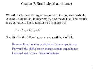
Small Signal Model PNP Transistor. Section 4.1-4.4,4.6. Schedule. Overview. Review. Small Signal Model. Section 4.4. Schematic of an Audio Amplifier. Microphone produces a small signal. How does the amplifier circuit respond to a small change in the input signal?

E N D
Small Signal ModelPNP Transistor Section 4.1-4.4,4.6
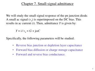
Small Signal Model Section 4.4
Schematic of an Audio Amplifier Microphone produces a small signal. How does the amplifier circuit respond to a small change in the input signal? How is the analysis performed? Small signal model
Small Signal Analysis (For a Circuit You have not Seen Before) • Replace each ideal DC voltage source with a small signal ground. • Replace each ideal DC current source with an open circuit. • Replace each transistor by its small signal model • Analyze the small signal equivalent circuit.
Small Signal Analysis (For a Circuit You have not Seen Before) • Analyze the Circuit by Inspection
Voltage Source RS should be 0 for a good battery! DC Voltage Source in Small Signal Analysis
Current Source RS should be infinity for a good battery!
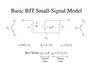
Small Signal Model (NPN) (PNP) • Statements that are always true for both NPN and PNP. • rπ is between B and E. • the direction of the dependent current source always points • from the collector to emitter. • 3. ro is always between B and C.
Question Replace Q1 and Q2 by their small equivalent circuit.
Change in the Collector Current Due to a Small Change in Base-Emitter Voltage If a signal changes the base-emitter voltage by a small amount, how much change is produced in the collector current?
Derivation of Transconductance Small signal model of Q1 If a signal changes the base-emitter voltage by a small amount, how much change is produced in the collector current?
But there is something else…. Small signal model A change in VBE creates a change in base current!
Example 4.10 Signal Generated By a microphone Small Signal Equivalent Circuit VBE=800 mV β=100 IS,Q1=3 x 10-16 A Question: If a microphone generates a 1 mV signal, how much change is observed in the collector and base current?
A Simple Amplifier Determine the output signal level if the microphone produces a 1 mV signal.
AC Ground • The voltage produced by a voltage source is constant. • The small signal model is concerned only with changes in quantities. • Therefore, a DC voltage source must be replaced with a ground in small signal analysis.
Example Small Signal Model
Output Resistance Due to Early Effect A larger reverse bias voltage leads to a larger BC depletion region. The effective base width (WB) is reduced. The slope of the electron profile increases. IC increases as VCE is increased.
Assumption • Assume that • The DC at Vout is 0.9 V • gm=1 mS Gain is approximately equal to –gmRC. Bias current is IC=gmVt R=(1.8V-0.9V)/26uA=34.6 Kohms Gain is -34.6.
Peak to Peak Voltage=67.78 mV 67.78 mV/2=33.9