Effective Coordinate Entry Systems in AutoCAD: Absolute, Relative, and Polar Methods
Discover the intricacies of coordinate entry systems in AutoCAD, covering the X and Y axes, absolute and relative coordinates, and angular measurements. Learn how to accurately plot points using coordinate pairs and understand the difference between absolute (specific distance from the origin) and relative (distance from a given point) coordinates. This essential guide also includes insights on angular measurement and polar coordinates, providing tips to ensure precision in your designs. Master the command line with confidence!

Effective Coordinate Entry Systems in AutoCAD: Absolute, Relative, and Polar Methods
E N D
Presentation Transcript
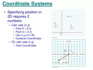
To create a line, place points at specific spots on the grid.
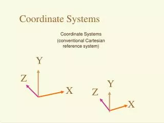
The location of the points is given by a coordinate pair, with the X coordinate first, then the Y.
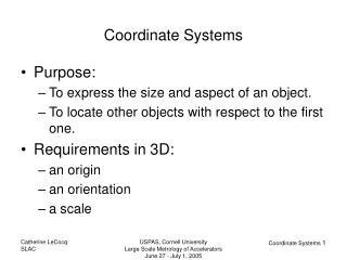
Two kinds of points in AutoCAD • Absolute: Points which are located a specific distance from the origin point of the XY coordinate axis. (0,0) • Relative: Points which are located a set distance away from a given object in the drawing area.
Absolute Coordinate Entry • When you want to draw an object with absolute coordinates, you will use a specific coordinate pair (x,x) for each point on the drawing. • For example, to draw the line in the previous slides, I would choose the line command, and when it asks for my first point, I would type (-4,-4). Then when it asks for the second point, I would type (5,3).
Relative Coordinate Entry • Most of the time you will not have an indication of where the origin is. You may need to draw a line from the endpoint of an existing line or object. • After you've entered one point, the next would be entered as @X,Y. This means that AutoCAD will draw a line from the first point to another point X units over and Y units up relative to the previous point.
Angular Measurement • AutoCAD measures angles in a particular way also. • When drawing lines at an angle, you have to begin measuring the angle from 0 degrees, which is at the 3 o'clock position. If you drew a line at 90 degrees, it would go straight up.
In this example, you are given information about the lines, but not the angle AutoCAD needs to draw the line from the start point. What you are given though, is (a) the knowledge that 0° is at the 3 o'clock position (b) the knowledge that 180° is at the 9 o'clock position and (c) the angle between 180° and the line you want to draw is 150°. With this information, you can figure out what angle you need. Here is a fool-proof way of getting the angle you need: • Start at the 0° position and measure counter-clockwise (+) to 180°. • From 180°, measure clockwise 150° (-) • Consider that you just went +180-150 and use that as an equation: +180-150=30
Polar Coordinate Entry • You would use this system if you know that you want to draw a line a certain distance at a particular angle. • You would enter this as @D<A. In this case, D is the distance and A is the angle. • Example: @10<90 will draw a line 10 units straight up from the first point.
Tips • Remember that X is always before Y (alphabetical). • Don't forget the '@' symbol when you are entering relative points. Any typing error or omission will give you results you don't want. • If you make a mistake and need to see what you typed, press F2 to bring up the text screen and check your typing. (press F2 to get back to your drawing.)