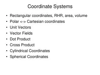
Coordinate Systems
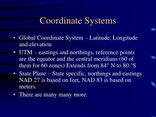
Coordinate Systems. In navigation, guidance, and control of an aircraft or rotorcraft, there are several coordinate systems intensively used in design and analysis. the geodetic coordinate system, the earth-centered earth-fixed (ECEF) coordinate system,

Coordinate Systems
E N D
Presentation Transcript
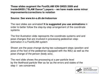
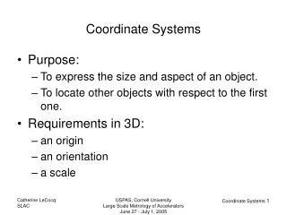
In navigation, guidance, and control of an aircraft or rotorcraft, there are several coordinate systems intensively used in design and analysis
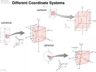
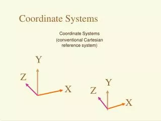
the geodetic coordinate system, the earth-centered earth-fixed (ECEF) coordinate system, the local north-east-down (NED) coordinate system, the vehicle-carried NED coordinate system, and the body coordinate system. coordinate systems
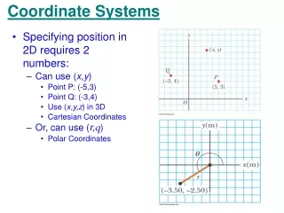
is widely used in GPS-based navigation system that characterizes a coordinate point near the earth’s surface in terms of longitude, latitude, and height (or altitude), which are respectively denoted by λ, ϕ, and h longitude measures the rotational angle (ranging from −180° to 180°) between the Prime Meridian and the measured point. The latitude measures the angle (ranging from −90° to 90°) between the equatorial plane and the normal of the reference ellipsoid that passes through the measured point. The height (or altitude) is the local\vertical distance between the measured point and the reference ellipsoid. Geodetic Coordinate System
It should be noted that the adopted geodetic latitude differs from the usual geocentric latitude(ϕ), which is the angle between the equatorial plane and a line from the mass center of the earth. position vector in the geodetic coordinate system is denoted by
the semi-major axis Rea the flattening factor f, the semi-minor axis REb, the first eccentricity e, the meridian radius of curvature ME, the prime vertical radius of curvature NE. Important parameters associated with the geodetic frame
The ECEF coordinate system rotates with the earth around its spin axis. As such,a fixed point on the earth surface has a fixed set of coordinates Earth-Centered Earth-Fixed Coordinate System
The origin (denoted by Oe) is located at the center of the earth. The Z-axis (denoted by Ze) is along the spin axis of the earth, pointing to the north pole. The X-axis (denoted by Xe) intersects the sphere of the earth at 0° latitude and 0° longitude. The Y-axis (denoted by Ye) is orthogonal to the Z- and X-axes with the usual right-hand rule. The origin and axes of the ECEF coordinate system are defined as follows:
The local NED coordinate system is also known as a navigation or ground coordinate system. It is a coordinate frame fixed to the earth’s surface. Based on the WGS 84 ellipsoid model Local North-East-Down Coordinate System
The origin (denoted by On) is arbitrarily fixed to a point on the earth’s surface. The X-axis (denoted by Xn) points toward the ellipsoid north (geodetic north). The Y-axis (denoted by Yn) points toward the ellipsoid east (geodetic east). The Z-axis (denoted by Zn) points downward along the ellipsoid normal. NESD axes are defined as the following
The vehicle-carried NED system is associated with the flying vehicle. Its origin and axes are given by the following: The origin (denoted by Onv) is located at the center of gravity (CG) of the flying vehicle. The X-axis (denoted by Xnv) points toward the ellipsoid north (geodetic north). The Y-axis (denoted by Ynv) points toward the ellipsoid east (geodetic east). The Z-axis (denoted by Znv) points downward along the ellipsoid normal. Vehicle-Carried North-East-Down Coordinate System
The body coordinate system is vehicle-carried and is directly defined on the body of the flying vehicle. Its origin and axes are given by the following The origin (denoted by Ob) is located at the center of gravity (CG) of the flying vehicle. The X-axis (denoted by Xb) points forward, lying in the symmetric plane of the flying vehicle. The Y-axis (denoted by Yb) is starboard (the right side of the flying vehicle). The Z-axis (denoted by Zb) points downward to comply with the right-hand rule. Body Coordinate System
ECEF and Local NED Coordinate Systems Pn = Rn/e(Pe −Pe,ref), where Pe,ref is the position of the origin of the local NED frame (i.e., On, normally the takeoff point in UAV applications) in the ECEF coordinate system, Rn/e is the rotation matrix from the ECEF frame to the local NED frame, which is given by