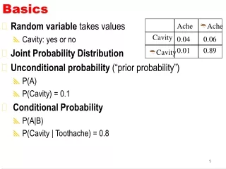
BASICS
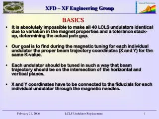
BASICS. It is absolutely impossible to make all 40 LCLS undulators identical due to variation in the magnet properties and a tolerance stack-up, determining the actual pole gap.

BASICS
E N D
Presentation Transcript
BASICS • It is absolutely impossible to make all 40 LCLS undulators identical due to variation in the magnet properties and a tolerance stack-up, determining the actual pole gap. • Our goal is to find during the magnetic tuning for each individual undulator the proper beam trajectory coordinates (X and Y) for the same K-value. • Each undulator should be tuned in such a way that beam trajectory should be on the intersection of the horizontal and vertical planes. • X and Y coordinates have to be connected to the fiducials for each individual undulator through the magnetic needles. LCLS Undulator Replacement
How to replace any of the LCLS undulators: • We are expecting that the variations in x coordinates between the different LCLS undulators will be within 800 – 1000 microns and the variation in Y coordinate will be within 30 – 50 microns. • Undulator supporting plates (on each side) have vertical and horizontal shims with the sufficient thickness to accommodate X and Y coordinate variations by grinding. • These shims should be precisely ground to get dimensions “A” and “B” exactly the same for all undulators with the precision 20 – 30 microns for the dimension “B” and 50 – 70 microns for the dimension “A”. • A true kinematic mount is not appropriate in my opinion . It will decrease rigidity of the whole structure without any benefit. LCLS Undulator Replacement
HOW TO MAKE ALL LCLS UNDULATORS IDENTICAL LCLS Undulator Replacement
SUPPORT ADJUSTING SHIMS – EXPLODED VIEW LCLS Undulator Replacement
SUPPORT ADJUSTING SHIMS LCLS Undulator Replacement
CONCLUSION • Test of the LCLS undulator replacement will be a part of SUT. • We intend to remove the dummy undulator off the girder and bring it back 5-6 times and verify optically and with the use of KEYENCE non-contact laser measurement the precision and repeatability of replacement. LCLS Undulator Replacement