Dry Etching, General Principles
Dry Etching, General Principles. Dr. Marc Madou, Fall 2012 Class 7. Dry etching: definition Pressure units and modes of gas flow Plasmas or discharges How to create a vacuum Plasmas: DC and AC Paschen curve Dry etching mechanisms Dry etching types and equipment Etching profiles:


Dry Etching, General Principles
E N D
Presentation Transcript
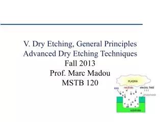
Dry Etching, General Principles Dr. Marc Madou, Fall 2012 Class 7
Dry etching: definition Pressure units and modes of gas flow Plasmas or discharges How to create a vacuum Plasmas: DC and AC Paschen curve Dry etching mechanisms Dry etching types and equipment Etching profiles: Sputtering Chemical Ion-enhanced Ion-enhanced inhibitor Etching profiles in physical etching Faceting Ditching Redeposition Comparing wet with Dry Etching Content
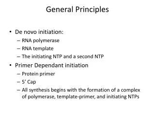
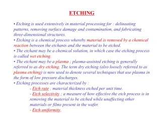
Dry etching: definition • Dry etching techniques are those that use plasmas (hot ionized gases) to drive chemical reactions or employ energetic ion beams to remove material. Dry-etching processes yield finer patterns than wet etching (surface tension !). These techniques also offers greater safety as large quantities of corrosive acids or bases are not required. • Within a dry etching reaction chamber the wafers lie directly in the plasma glow (also called a discharge), where reactive ions are accelerated towards the wafer (often biased). The ions are a species likely to attack the substrate material chemically with or without selectivity.
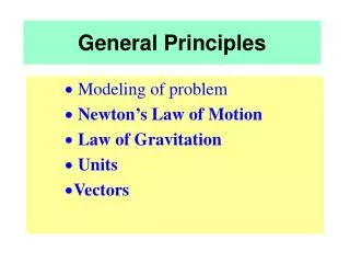
Pressure units • Definitions of Vacuum Regimes: 1) Rough Vacuum: ~0.1- 760 torr (atmospheric pressure is 760 torr) 2) Medium Vacuum:~ 0.1 to 10-4 torr 3) High Vacuum: ~ 10 -8 to 10-4 torr 4) Ultrahigh Vacuum: < 10 -8 torr • 2 modes of gas flow: • Viscous Flow regime:gas density (pressure) is high enough, many moleculemolecule collisions occur and dominate the flow process (one molecule “pushes” another). Collisions with walls play a secondary role in limiting the gas flow. • Molecular flow regime: gas density (pressure) is very low, few molecule- molecule collisions occur and molecule- chamber wall collisions dominate the flow process (molecules are held back by walls). See further below for mathematical expressions for these two regimes.
How to create a vacuum • Visit on your own time http://et.nmsu.edu/ETCLASSES/vlsi/files/ARTICLE.HTM on vacuum pumping (take the quiz at the end). • The first thing that all basic systems have is a rough-pumping system. It is used to reduce the pressure from atmospheric pressure in the chamber to a lower pressure level that other low-pressure systems can use. Then there has to be a fine-pumping system that must be able to attain sufficient pumping speed to handle the outgassing from the work produced in the chamber of the vessel. There must also be vacuum gauges that determine the pressure at certain points of the system. • Pumps: • Diffusion pumps operate from 10-4 Torr to 5x10-11 Torr. Diffusion pumps operate by boiling a fluid, often hydrocarbon oil, and angling the dense vapor stream in a downward conical direction back into the pump boiler. Gas molecules from the system that enter the oil curtain are pushed toward the boiler by momentum transfer from the large fluid molecules. Diffusion pump
Mechanical pump. Pump operation is based on bulk flow of gas; hence the pump works in the viscous flow regime. Used for obtaining "rough" vacuum (10-3 Torr), which is the lower limit of the viscous flow regime Simplest plasma chamber is 2 parallel plate electrode set (anode and cathode) in a low pressure Argon filled chamber (e.g. 0.001 to 1 Torr). The two electrodes are positioned parallel to each other, with the top electrode and chamber walls electrically grounded while the lower electrode and substrate holder are connected through a dc-blocking capacitor and matching network to a 13.56 MHz F generator (AC plasma case) Plasmas : DC and AC Principle of mechanical operation: (1) begin expansion cycle (2) seal off expanded volume (3) compress gas out exhaust
Plasmas: DC and AC • Apply 1.5 kV over 15 cm--field is 100-V/cm. Breakdown of Argon when electrons transfer a kinetic energy of 15.7 eV to the Argon gas. • These energetic collisions generate a second electron and a positive ion for each successful strike. • If the two electrons reenergize creating an avalanche of ions and electrons we get a glow or plasma. • At the start of a sustained gas breakdown a current starts flowing and the voltage drops to about 150 V. • To sustain a plasma, a mechanism must exist to generate additional free electrons after the plasma generating ones have been captured at the anode. • The additional electrons are formed by ions of sufficient energy striking the cathode (emitting secondary Auger electrons). • This continuous generation provides a steady supply of electrons and a stable plasma. • Plates too close: no ionizing collisions (not enough energy), too far too many inelastic collisons in which ions loose energy.
Plasmas : DC and AC • Plasma dark spaces: dark because the higher energy electrons cause ionization rather than light-generating excitation. • Plasma is always positive, this follows from kinetics: for a random velocity distribution the flux of ions and electrons upon a surface is given by: where n is a density and <v> an average velocity. Ions are 4000 to 100,000 times more heavy than electrons so the average velocity of electrons is much larger. Electron flux to surrounding surfaces is larger resulting in a positive charge on the plasma. • Assymetry of voltage distribution: electrons move faster away from the cathode than positive ions are accelerated towards it larger space charge (also the dark space is larger at the cathode).
The largest voltage drop is in front of the cathode where charged particles will experience their largest acceleration. The cathode gets etched the anode does not !! Substrates to be etched are laid down on the cathode. Efficiency or ‘strength’ of a particular plasma is evaluated by the average electron energy (temperature) ion energy (temperature) electron density (e.g. 109 and 1012 cm-3) ion density (e.g. 108 to 1012 cm-3) neutral species density (e.g. 1015 to 10 16 cm -3) ion current (e.g. 1 to 10 mA/cm 2). The ratio between ionized species and neutral gas species is 10-6 to 10-4. Plasmas : DC and AC
(I) (II) (Equation III) (Equation IV) Plasmas : DC and AC • An important quantity to describe a plasma is the ratio of electrical field over pressure (Equation I). With increasing fields the velocity of free electrons or ions increases (~E) but an increase in pressure decreases the electron or ion mean free path (~1/P).The mean free path (l) is given by Equation (II) where nv is the number of molecules per unit volume, • The number of molecules per unit volume, nv, can be determined from Avogadro's number and the ideal gas law, leading to Equation (III) • The bombarding flux of ions on the cathode is given by Equation (VI):
Plasmas : DC and AC • AC plasma’s for etching insulating surfaces. • Capacitor makes voltage distribution assymetric in this case. • A DC self bias results. • Etching energy: • Plasma energy: • Self bias:
Reactive species generation (1) Diffuse to the solid (2) Adsorption at the surface (3) Reaction at the surface (4) Reactive cluster desorption (5) Diffusion away from the surface (6) Dry chemical etching mechanisms
Continuous dry-etching spectrum low pressure <100 millitorr: physical sputtering unselective directional radiation damage 100 millitorr range:RIE physical and chemical directional more selective than sputtering higher pressures:plasma etching chemical (10-1000 times faster) --see extreme example, gas phase etching with XeF2 (not really a plasma) isotropic more selective least damage Dry chemical etching mechanisms
Dry chemical etching mechanisms: purely chemical • XeF2 Gas Phase Etching (high pressure, chemical only) • no plasma (just pump) • 10 µm/min • no damage • isotropic • very selective (Si over Al, photoresist, oxide and nitride) • CMOS compatible
Dry chemical etching mechanisms: Physical-chemical etching: Energy-driven anisotropy
Dry chemical etching mechanisms: Physical-chemical etching: Inhibitor-driven anisotropy
Dry etching types and equipment • RIE chamber with load lock
Dry etching types and equipment : RIBE vs. CAIBE • CAIBE is RIE in a triode system (e.g. 10, 000Å/min) • RIBE ion is reactive and etches (e.g. 100Å/min)
Etching profiles in dry etching • Sputtering: directional, physical. • Chemical: non-directional (diffusion). • Ion-enhanced energetic: directional. • Ion-enhanced inhibitor: directional.
Etching profiles in physical etching • Faceting: angle of preferential etching • Ditching (trenching): sometimes caused by faceting • Redeposition: rotational stage might reduce this effect.
Homework • 1 How is a DC plasma created and how does an RF plasma differ? Why is a plasma always positive with respect to the reactor vessel walls? In which etching setup would you prefer to etch an insulator? Is space positively charged? • 2 Detail the different dry etching profiles available and how you obtain them. • 3. Explain the DC breakdown voltage versus electrode distance curve (Paschen’s law) and how it is relevant to dry etching. How is miniaturization of an electrode set equivalent to creating a local vacuum? • 4. Discuss the etch profiles in physical etching. Also draw profiles exhibiting faceting, ditching, and redeposition. • 5. Design a process to fabricate a polyimide post 100µm high and 10 µm in diameter on a Si cantilever. The Si cantilever must be able to move up and down over a couple of microns.