Download
1 / 28
280 likes | 399 Views
XP 833 Halo Current Dependencies on I P /q 95 , Vertical Velocity and Halo Resistance. Stefan Gerhardt, and Members of the Macroscopic Stability Topical Science Group. Background.

E N D
XP 833 Halo Current Dependencies on IP/q95, Vertical Velocityand Halo Resistance Stefan Gerhardt, and Members of the Macroscopic Stability Topical Science Group
Background • Halo Current: When vertical position control of the plasma is lost during a disruption, the plasma comes in contact with the plasma facing components (PFCs). Decay of the poloidal and toroidal flux lead to voltages, and thus are driven currents that link the outer plasma region (halo) and PFCs • Large electromagnetic loads on in-vessel component (JhaloxBT) …main load on ITER components for slow current quenches. • New diagnostics installed for the FY08 run have motivated a new proposal. • Goal of this XP: generate large halo currents and study their dependencies of various parameters. Works towards NSTX programmatic goal of understanding ST disruption dynamics. Provides timely information for LLD design.
Halo Current Diagnostics For CY08 Run Rogowskis on the CSC CSCL1, CSCL2, CSCU1 Two Arrays of 6 BT coils Inner Ring: Just Outside the CHI Gap Outer Ring: Just Outside the OBD Difference Between These: Current into the OBD Two Pearson CTs on CHI Bus Current from inner to outer vessel NSTX Is Only Device with this Broken Halo Current Path Part of XP is designed to study this “feature”.
Type 1: Shot 127277, Upward Going VDE Linking CHI Gap • Down the outer vessel, up the center column • In vessel current is clockwise when facing in the positive toroidal angle
Type 2: Shot 127077, Downward Going VDE Linking CHI Gap • In vessel current is counter clockwise when facing in the positive toroidal angle
Type 3: Shot 126743, Downward Going VDE Linking Inner Ring Only • In vessel current is counter clockwise when facing in the positive toroidal angle
Type 4: Shot 127492, Downward Going VDE Linking OBD and SPP • In vessel current is counter clockwise when facing in the positive toroidal angle
Halo Current depends on Direction of Vertical Motion OBD=(Outer Ring)-(Inner Ring) Every Point has 1msec LRDFIT01
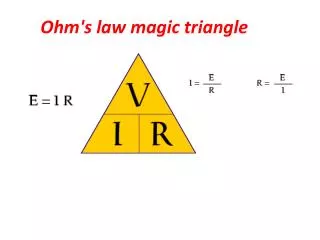
Ohm’s Law Explanation of Halo Currents (I) Halo is force-free, so Ohm’s law looks like: Can Wall Resistance Be Neglected ? Relate the electric fields to voltages (<<1) is the fraction of the poloidal path in the wall Define the poloidal halo current as: The Halo Ohm’s law becomes: The wall Ohm’s law becomes: Vessel Resistance Can Be Neglected When Current Avoids the CHI Bus Combine these to form a total Ohm’s law *P.J. Knight et al, Nuclear Fusion 40, 325 (2000)
Ohm’s Law Explanation of Halo Currents (II) Model Provides Estimate of Maximum Halo Current For Highly Conducting Halo This scaling observed in MAST, JET, JT-60, ALCATOR C-Mod, Compass-D… Dependencies to Be Studies • Halo resistance with all else fixed. • Ip/q95 with all else fixed • Variation with quench rate at all else fixed. *P.J. Knight et al, Nuclear Fusion 40, 325 (2000)
The Halo Current Depends on the VDE Growth Rate at Conventional A. Y. Neyatani, et al, Nuclear Fusion 39, 559 (1999) V. Riccardo, Plasma Phys. Control. Fusion 46, 925 (2004) This would correspond to large poloidal driving voltages…check in NSTX by varying the downward velocity.
XP811 data showed large Halo Currents • Helium PF1A shot with k=1.8, vertical position control frozen at t=0.3. • No scan over Ip, BT, or shape, only the duration of the freeze. • Disruptions went up or down. • Downward disruptions typically partially linked the CHI gap. • Use this as one of two equilibria in a scan of Ip/q95 to test the case where the CHI buss is partially in the loop. OBD CSCL1 Pearson Inner Ring (Essentially unresolved-> binary up or down)
Examples Show Main Requirements of XP • Disruptions Must go DOWN • Explore cases that link the CHI Buss, and cases that do not. • Between shot reconstructions must be available with fast time resolutions (EFIT01 at 1 msec during the XP). • Would like to have the fast camera viewing the entire lower divertor…correlation with toroidal peaking.
Target is 127070: 600 kA Helium Gap-Control Shot From XP 811, Freeze Control at 250 msec • Parameters • 600 kA target • =1.9 • drsep=1mm • R0=.84 m • Outer Gap=10-12cm • l, t=.4 • W=30kJ • BT=0.45 • Freeze the PF3 voltages at 0.25 sec. for remainder of shot. • Introduce 5msec step in PF3 voltages using the Voffset waveform to force plasma down. (typically 150 V on PF3, use 10V kick)
Scan #1: IP/q95 scan at high l • Motivation: Halo Current observed to scale like some fraction of IP/q95Ip2/BT. • Fill in a matrix to get a factor of 3 variation in IP/q95. • Take points at end of scan twice. 1.8 (2 )
Develop a shot where halo currents reliably link the SPP and OBD Try to get the plasma to land like this. Implement series of step changes to the reference shot • Turn of PF1A • Increase PF2 Pulling. • Decrease PF3 Pushing (i.e. make less negative) • Increase PF3l, so bias more downward. Keep Freeze On, to Get a Wide Scan of Halo Current Parameters
Turn off PF1A =1.9, l=.4 , u=.4 =1.68, l=.326 , u=.326 R0=0.84, R/a=1.31
Increase PF2 PF2=4.2kA PF2=11.9kA =1.68, l=.326 , u=.326 R0=0.84, R/a=1.31 =1.80, l=-.173, u=.210 R0=.878, R/a=1.56
Reduce Pushing From PF3 PF3=-4.74kA PF3=-2.74kA =1.80, l=-.173, u=.210 R0=.878, R/a=1.56 =1.85, l=-.153, u=.163 R0=.891, R/a=1.67
Bias the Plasma Down With 600A in PF3L PF3=-2.74kA PF3U=-2.74kA PF3L=-2.14kA =1.802, l=-.08, u=.118 R0=.895, R/a=1.7, drsep=-7mm =1.85, l=-.153, u=.163 R0=.891, R/a=1.67, drsep=0
Suggested Procedure For Change 1: Zero PF1A, Change PF2s as 4.2 kA7.2kA (7kA/MA1.2 kA/MA) 2: Change PF2s as 7.2kA 11.9 kA (1.2 kA/MA2kA/MA) 3: Change PF3s as -4.74kA-3.74kA (-7.9kA/MA -6.23 kA/MA) 4: Change PF3s as -3.74 kA-2.74 kA (-6.23 kA/MA -4.56 kA/MA) 5: Bias Down: Add 600 A to PF3L (change of 1kA/MA) Keep Freeze On, and stop changes when currents link SPP and OBD Last Resorts: Decrease the Outer Gap Increase Freeze Voltage Offset 1 (3.0)
Scan #2: IP/q95 scan at low l • Motivation: Halo Current observed to scale like some fraction of IP/q95Ip2/BT. • Fill in a matrix to get a factor of 3 variation in IP/q95 • Take points at end of scan twice. 1.8 (4.8)
Scan #3: VDE “Impact” Scan • Want to scan the velocity of the downward going plasma….will it modify the halo current magnitude? • Scan the duration and magnitude of the offset during the freeze time. • Use high or low configuration depending on which is more repeatable. …or… 1 (5.8)
Scan #4: D2 vs HeComparison • Most operations are in D2, but this reference shot is in He…does this impact the result? • Propose to redo parts of scan 1 or 2, depending on which is more interesting, in D2. • 5 minute glow, maybe 10 minute cycle time (maybe 12?) • First shot in this scan should be proceeded by 2 minutes D2 glow, then 7 minutes of He glow. 1.6 (7.4)
Scan #5: halo scan to vary the halo resistivity • Use Injector 1 system, to puff Neon into lower divertor during downward going VDE. • Time neon wavefront to enter just as downward motion begins (require pre-XP evaluation of Neon Flow rate from injector 1, 100Torr-liter/sec typical). • Be careful of the prefill and the glow...don’t use Neon for either. • Scan total amount of gas entering divertor, by varying the plenum pressure (typical particle inventory is 10-15 Torr-Liters). • Need to calibrate the injector before the XP…have talked to Scott and Bill. • Use high or low configuration depending on which is more repeatable. 0.6 (8)
Other Details of Setup • Injector 1: Neon • Injector 2: D2 prefill, to about 1.6x10⁻⁵ torr for reference shot, also all fueling for D2 cases. • Injector 3: He fill and glow during D2 period. • NBI, CHI, HHFW: Not used • BT: .3-.55 T • Ip: 500-700 kA
Shot List, Min (+Contingency) Full Day (8hours*6 shots/hour=48 shots) • Startup: 1 (+1) shots • IP/q95 scan at high l : 11 (+3) shots • Low l Shot Development: 6 (+2) Shots • IP/q95 scan at low l : 11 (+3) shots • VDE Velocityscan: 6 (+2) shots • D2 Comparison: 7 (+2) shots • Neon Injection: 3 (+2) shots • Total: 45 (+60) shots 1/2 Day(4hours*6 shots/hour=24 shots) • Startup: 2 (+1) shots • IP/q95 scan at high l : 8 (+3) shots • Low l Shot Development: 6 (+2) Shots • IP/q95 scan at low l : 8 (+3) shots • Total: 24 (+9) shots