Download
1 / 40
711 likes | 2.05k Views
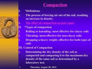
Field Compaction Equipment and Procedures. Dr. Talat Bader. Objective of field Compaction & Control Parameters. The objective of compaction is to stabilize soils and improve their engineering behavior

E N D
Field Compaction Equipment and Procedures Dr. Talat Bader
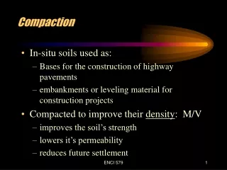
Objective of field Compaction&Control Parameters • The objective of compaction is to stabilize soils and improve their engineering behavior • It is important to keep in mind the desired engineering properties of the fill, dam, road, etc… • The density of the fill in addition to the water content should be observed. From Holtz and Kovacs, 1981
Design and Selection of Fill Materials • Survey the local soil sources that could possibly be used. • Obtain soil samples from each source (borrow), and perform the necessary laboratory tests to classify the soil via either AASHTO or the UCS systems to define the properties required for design. • The classification itself will often tell whether or not a given soil is suitable for an intended application. • Soils with large shrinkage ratios (SR) should be avoided. • Soils with high plasticity indices (PI) should be avoided, since they indicate a tendency to shrink/expand. • Organic matter which can decay should generally be avoided as fill material unless special precautions are taken.
Design and Selection of Fill Materials 3)Once a soil is found to be suitable, for an intended application, perform the necessary moisture-density study. 4) If local codes/guidelines are not provided, a study would be needed to determine the minimum relative field compaction of the soil. Factors would be: • required shear strength of the soil • maximum allowable settlements under design loads. • After the earth structure is designed, • The compaction specifications are written. • Field compaction control tests are specified, • And the results of these become the standard for controlling the project.
From Holtz and Kovacs, 1981 Specifications • End-product specifications • This specification is used for most highways and building foundation, as long as the contractor is able to obtain the specified relative compaction , how he obtains it doesn’t matter, nor does the equipment he uses. • Care the results only ! • Method specifications • The type and weight of roller, the number of passes of that roller, as well as the lift thickness are specified. A maximum allowable size of material may also be specified. • It is typically used for large compaction project.
Standard & ModifiedProctor Test Modified Dry Density (gd) Standard Water Content (w)
1.9 120 S = 100% 1.8 110 Dry Density (lb/ft3) Dry Density (Mg/m3) 1.7 100 90 1.6 1.5 2 4 3 6 5 1 10 15 20 25 Water Content (w) (From Lambe and Whitman, 1979) Field & Laboratory Compaction • It is difficult to choose a laboratory test that reproduces a given field compaction procedure. • The laboratory curves generally yield a somewhat lower optimum water content than the actual field optimum. • The majority of field compaction is controlled by the dynamic laboratory tests. Curve 1, 2,3,4: laboratory compaction Curve 5, 6: Field compaction
The Bader,s Watering
Smooth-wheel roller (drum) • 100% coverage under the wheel • Contact pressure up to 380 kPa • Can be used on all soil types except for rocky soils. • Compactive effort: static weight • The most common use of large smooth wheel rollers is for proof-rolling subgrades and compacting asphalt pavement.
Smooth-wheel roller (drum) • Suitable for: • well-graded sands and gravels • silts and clays of low plasticity • Unsuitable for: • uniform sands; • silty sands; • soft clays
Direction of Motion Pneumatic (or rubber-tired) roller • 80% coverage under the wheel • Contact pressure up to 700 kPa • 7 to 13 wheels are arranged in two rows. • Compactive effort: static weight and kneading.
Pneumatic (or rubber-tired) roller • Small Tired Roller • Straight rolling • Wobble Action • Heavy Tire Roller • 50 to 100 tons • Tire pressure 90-150 psi • Additional weight • Water, Sand or Steel • Can be used for both granular and fine-grained soils. • Can be used for highway fills or earth dam construction.
Pneumatic (or rubber-tired) roller • Suitable for: most • Coarse • fine soils. • Unsuitable for: • very soft clay • highly variable soils
Sheepsfoot rollers • Has many round or rectangular shaped protrusions or “feet” attached to a steel drum • 8% ~ 12 % coverage • Contact pressure is from 1400 to 7000 kPa • It is best suited for clayed soils. • Compactive effort: static weight and kneading.
foot Heavy footed compactors with large feet that fully penetrate a loose lift of soil are ideal. Minimum specifications: • weight : 18000 kg • foot length: 18 cm to 20 cm • number of passes: 5 (a) loose lift of soil compacted lift (b) loose lift of soil compacted lift
Drum Drum may be loaded with Water Soil Loaded weight Vary from 6,000 # 80,000 # Drum Length from 48” to 72” Drum Diameter from 40” to 72”
Sheepsfoot rollers • Suitable for: • fine grained soils • sands and gravels, with >20% fines • Unsuitable for: • very coarse soils • uniform gravels
Tamping foot roller • About 40% coverage • Contact pressure is from 1400 to 8400 kPa • It is best for compacting fine-grained soils (silt and clay). • Compactive effort: static weight and kneading.
Mesh (or grid pattern) roller • 50% coverage • Masses range from 5-12 Tones • Contact pressure is from 1400 to 6200 kPa • Compactive effort: static weight and vibration. • High towing speed, the material is vibrated, crushed, and impacted. • Suitable for: • well-graded sands • soft rocks • stony soils with fine fractions • Unsuitable for: • uniform sands • Silty sands • Very soft clays
Vibrating drum on smooth-wheel roller • Vertical vibrator attached to smooth wheel rollers. • The best explanation of why roller vibration causes densification of granular soils is that particle rearrangement occurs due to cyclic deformation of the soil produced by the oscillations of the roller. • Compactive effort: static weight and vibration. • Suitable for granular soils
Vibrating Plate & Power Rammer • Range from hand-guided machines to larger roller combinations • Suitable for: • most soils with low to moderate fines content • Unsuitable for: • large volume work • wet clayey soils • Also called a 'trench tamper' • Hand-guided pneumatic tamper • Suitable for: • trench back-fill • work in confined areas • Unsuitable for: • large volume work
C E 3 5 3 Dr. T A L A T B A D E R 100 % Clay 100 % Sand Rock Compactive Effort Sheepsfoot Static wt, Kneading Grid Static wt, Kneading Vibratory Static wt, Vibration Smooth steel drums Static wt Multitired pneumatic Static wt, Kneading Heavy pneumatic Static wt, Kneading Towed tamping foot Static wt, Kneading High speed tamping foot Static wt, Kneading, impact, Vibration Compactor Zones of Application
Equipments & Soil Type • Special compaction equipment is then used to compact this lift of soil: Equipment Type • Smooth-Wheeled Rollers • Pneumatic Rubber-Tired Rollers • Sheepsfoot Rollers • Vibratory Rollers • Vibratory Tampers Soil Type • sands & gravels • silts & clays • silts & clays • sands & gravels • sands & gravels
Variables-Vibratory Compaction • There are many variables which control the vibratory compaction or densification of soils. Characteristics of the compactor: • (1) Mass, size • (2) Operating frequency and frequency range Characteristics of the soil: • (1) Initial density • (2) Grain size and shape • (3) Water content Construction procedures: • (1) Number of passes of the roller • (2) Lift thickness • (3) Frequency of operation vibrator • (4) Towing speed
Dry density (lb/ft3) 95 100 105 110 0 1 2 Depth (ft) Initial fill density 3 4 5 Holtz and Kovacs, 1981 6 40 50 60 70 80 90 100 Relative Density (%) Roller Passes When compacting past five or so coverage's, there is not a great increase in density • 240 cm think layer of northern Indiana dune sand • 5670 kg roller operating at a frequency of 27.5 Hz. 02 roller passes 05 roller passes 15 roller passes 45 roller passes
Dry density (lb/ft3) 95 100 105 110 0 1 2 Depth (ft) Initial fill density 3 4 5 Holtz and Kovacs, 1981 6 40 50 60 70 80 90 100 Relative Density (%) Roller Passes • Low Compaction at the surface • Max. Dr. is approximately ½ meter bellow the surface. • Most effective compaction is done during the first 5-7 passes. 02 roller passes 05 roller passes 15 roller passes 45 roller passes
Relative density (%) 50 60 70 80 90 0 0.0 1 0.5 Minimum allowable relative density = 75% 2 Depth (ft) (m) 18in 3 1.0 4 0.5 5 Density-depth relationship for large lift height using 5 roller passes 6 Determine the Lift Height • For most compaction equipment, lift thicknesses should typically be on the order of six inches (6") or 15cm if no experience or testing
Relative density (%) 50 60 70 80 90 0 0.0 1 0.5 2 Depth (ft) (m) 3 1.0 4 0.5 5 Density-depth relationship for large lift height using 5 roller passes 6 Determine the Lift Height • For most compaction equipment, lift thicknesses should typically be on the order of six inches (6") or 15cm if no experience or testing
F The Wheel of compaction equipment Lift Thickness • If lift thicknesses are too large: • Soil at the top of the lift will be well-compacted. • Soil at the bottom of the lift will not be compacted. Why? • This is sometimes called the Oreo-Cookie effect. High stress region is well-compacted Low stress region is not Well compacted
Dry density (lb/ft3) 95 100 105 110 0 1 2 Depth (ft) 3 4 5 6 40 50 60 70 80 90 100 Relative Density (%) Frequency • Compacted Density increases with increasing operation frequency. • The operating frequency should be at least as large as the resonant frequency to obtain the most efficient use of the 30 Hz 20 Hz
150 sand Well-graded 140 Gravelly sand Gravel-sand-clay 130 Gravelly sand 120 Roller wt. in lb = 3600 = 5800 = 7500a = 7500b = 17000 110 Clay soil Heavy clay Heavy clay 100 Uniform sand Heavy clay 90 1000 2000 3000 Frequency The frequency at which a maximum density is achieved is called the optimum frequency. Dry Density (lb/ft3) Vibration frequency (cpm)
v 3.0 Perpendicular to roller path h 2.0 Dry Density (lb/ft3) 1.0 Parallel to roller path 20 0 4 8 12 16 Stresses Horizontal stress measurements indicated that lateral stresses are much grater than at rest condition. Lateral stresses were found to increase with Number of passes Operating frequencies
1.76 110 1.64 100 1.52 1.40 090 1.28 Roller Coverage 080 Mg/m3 Dry Density (lb/ft3) 140 2.00 1.90 130 1.80 120 0.75 mph 1.70 1.50 mph 110 2.25 mph 1.60 100 20 0 4 8 12 16 Roller Travel Speed For a given number of passes, a higher density is obtained if the vibrator is towed more slowly. Heavy clay (moisture = 21 %) For the same speed, the higher the number of passes the higher the density Well graded sand (moisture = 7.5 %)
Thank you Question Time Dr. Talat Bader