Download
1 / 39
430 likes | 1.34k Views
Explore essential EMC standards and tests for ensuring product safety in a global market. Learn about EMC compliance strategies, real-world effects, and energy measurements. Discover common EMC tests and operational modes to ensure effectiveness.

E N D
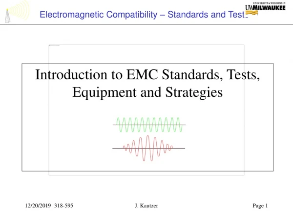
Introduction to EMC Standards, Tests, Equipment and Strategies J. Kautzer
EMC = Electro-Magnetic Compatibility Definition: The ability of a product to coexist and safely operate within a set of electromagnetic stresses while not inducing undue electromagnetic stresses Example: Use of cell phone on an operating aircraft is prohibited because - Navigational equipment may be effected from field emissions of the phone These EM stresses are standardized and refined into individual tests which are designed to either measure or induce real world effects J. Kautzer
Requirements Flowdown:Global Mfgs Typical Quality Policy • States that Company X is committed to comply with the Quality, Safety and Performance regulations of all countries where its products and services are offered This implies conformance to many standards which in turn call for compliance to other standards. J. Kautzer
Medical Equipment Example • New products destined for International Sales mustbe certified to safety standards IEC60601-1 and UL2601-1 as required to show objective evidence that the products are safe. Definition: IEC60601-1 = International Electrotechnical Commission Standard for Medical Electrical Equipment- Part 1, General Requirements for Safety (Many times referred to as IEC601-1 or simply “601”) Definition: UL2601-1 = Underwriters Laboratories Standard for Medical Electrical Equipment - Part 1, General Requirements for Safety Above includes sections on protection from electric hazards, mechanical hazards, excessive radiation, flammabilities, environmental conditions, constructional requirements, and labeling. J. Kautzer
Medical Equipment Example • The IEC60601-1 Safety standard, along with the equivalent US domestic safety standard, UL2601-1, call for IEC60601-1-2 EMC standard Definition: IEC60601-1-2 = IEC Standard for Medical Electrical Equipment - Part 1-2: General Requirements for Safety - Collateral Standard for Electromagnetic Compatibility - Requirements and Test (Many times referred to as IEC601-1-2 or simply the -2 standard) The IEC60601-1-2 standard calls for the use of several IEC and other Standard Tests as described herein Final draft of 2nd Edition of the above standard was approved by the IEC in July of 2001. J. Kautzer
EMC Compliance Has Been Mandated in Many Countries Most Notably in the EC (formerly EEC)EC - European Community • General EMC Directive: 89/336/EEC - 3 May 1999 • Medical Device Directive (MDD): 93/42/EEC - 14 June 1993 • R&TTE Directive: 1999/5/EC - 9 March 1999 - Radio and Telecommunications Terminal Equipment and mutual recognition of their conformity • EN 61000-6-2: General Industrial Equipment Immunity Standard • EN 50081-2: General Industrial Equipment Emissions Standard • EN55011: Referenced by EN50081-2, Emission Std for Industrial, Scientific and Medical products • EN61000-6-4: Effective 1 July, 2004, replaces EN50081-2 & EN55011 as Emission Std for Industrial, Scientific and Medical Products J. Kautzer
In the EU the CENELEC body harmonized many of the IEC standards into EN or European Norm (Government) standards. For example (Medical Device Safety Standard); IEC60601-1 first published in 1993 became EN60601-1 by 1996 For example (Medical Device EMC Std called by –1 above) IEC60601-1-2 Ed2 first published in 1998 became EN60601-1-2 by 2003 J. Kautzer
What are Real World Effects? • Static Discharge by Human Contact • Indirect Lightning Strike Effects • Power Line Surges • Power Line Brown Out and Drop Outs • Power Distribution Reclosures • Cell Phone or Telemetry Transmissions • Field Discharges from Equipment, Lights, Lasers, etc J. Kautzer
ENERGY • EMC compliance is all about measuring energy emitted by the product or …... • Measuring the response of the product to externally induced energy or energy disturbances J. Kautzer
Basic Stresses (Energy Types) • Alternating Electrical Fields • Alternating Magnetic Fields • Conducted Voltages/Currents • Capacitively Coupled Voltages • Electrostatic Voltages • Input Power Source Degradations J. Kautzer
EM Energy EM Energy EM Energy DEVICE DEVICE EMC Tests are divided into 2 Main Categories/Strategies • Emissions - Tests that measure in some way the amount of certain EM energies the device emits or induces • Susceptibility - Tests that measure in some way the effect or responses that EM stresses have on the device performance and safety J. Kautzer
Common Strategies - Test Effectiveness • Like many other Eng or Mfg tests, the quality of the test depends upon minimizing the possibility that a failure can escape. • To this end, all operational modes of a product need to be considered but …. Not necessarily used in all tests. J. Kautzer
Common Strategies - Operational Modes • Modes of Operation - All modes of product operation should be defined & if applicable, tested • Examples: • Idle, Standby, Offline, • Boot, Application, File Send, other SW functions • Battery Powered and Battery Charging (UPS Backups) • Data Xfer to Disk or CD Writing • Xmit, Receive, Measure, Configure, etc J. Kautzer
Common Strategies - Product Options • Product Options and Accessories - All applicable options should be evaluated in the same test if possible or mutually exclusive if necessary • Examples: • Inteface Cables • Metal Bracket Hangers (Metal Grab Bars) • Operator Console Stands, Pedestals, Monitors • UPS Backups, AC charging modules • Wall Plates • External Network Connections, Option Cables, etc J. Kautzer
Common Strategies - 2 Basic Test Types • Certification Test - Official tests used to show objective evidence of satisfying spec such as IEC60601-1-2. • Engineering Test - Test used for baselining a product but not necessarily using official equipment and process for official certification results. Often Eng tests use higher levels of stress. • Technical Justification - Formal document which may utilize previous certification or engineering test data that justifies a claim of compliance. J. Kautzer
Common Strategies - Subsystems vs System • System Test - Defined as a test of a full end user product. System must be certification tested and/or show compliance to all applicable tests from parent standard such as IEC60601-1-2. Systems in production are retested typically 1/yr as an audit process to show compliance. • Subsystem Test - Defined as a test of one element or subsystem which may not be an end user product. SS test necessity depends on System Cert strategy as well as CE marking of the SS but is always beneficial. J. Kautzer
EM Energy EM Energy DEVICE Strategy Differences • Emissions Tests - Allowable limits are well defined and a strategy is employed to find the maximum energy the product will induce • Susceptibility Tests - Stress levels are well defined and a strategy is employed to gauge and classify the immunity response level of the product to find the highest stress sensitivities DEVICE J. Kautzer
EMISSIONS • Radiated - RF (Radio Frequency) Electric Field measurements taken between 30 MHz and 1 GHz • Conducted - Voltage Measurements made on input power lines between 150 kHz and 30 MHz • Requires Product to be Powered on 50 Hz J. Kautzer
t T Typical Digital Signals and their Emissions Implications Source: Ford EMC Design Guide for PCB Fourier Spectral Components of square wave Where; DC = Duty Cycle (%) = t/T = d Max Amplitude = 2A x DC tr = 10-90% signal rise time tf = 90-10% signal fall time Periodic Digital Signal Spectral Content Well Beyond Fundamental Frequency J. Kautzer
Wavelength and Frequency of Signals lmeters= 300 / f(Mhz) J. Kautzer
Near vs Far Field Effect Transition Point Transition Point meters = l/2p= 150 /p f(Mhz) Fields closer than this distance tend to be complex and modeling may be difficult Far Field Electric Strength E Field v/m= (30 P)1/2 / r Where; r is distance from antenna in meters P is effective radiated power in watts J. Kautzer
Max Log Far Field Electric Strength from a Current Loop E Field diff mode dBuV/m= ~20 log{2.63x10⁻⁸ (A fn2 In) /r} dBuV/m Max Far Field Electric Strength from a Loop with Perimeter < l/4 E Field v/m= ~ 1 + (l /(2 p r))2 Near field can be approximated by multiplying above 2 equations together J. Kautzer
Max Far Field Electric Strength from a Small Loop at 1 Meter Distance Loop Area = 1x5cm = 0.0005m2 Clock Frequency = 10Mhz Imax = 10mA Tr = Tf = ~ 5nS (Med CMOS) Note Peak Field Strengths 5-13X Fundamental Freq J. Kautzer
EMISSIONS • Governed by CISPR11/EN55011 and other CISPR stds: International Special Committee on Radio Interference • Product classified depending on if RF energy is intentionally used: Group 2 (MR for example) or Group 1 • USLs Defined by Product intended application • Class A: Non Domestic Use • Class B: Domestic Use, More stringent J. Kautzer
RADIATED EMISSIONS • Electric Field is measured on a calibrated site using a receiving antenna and attempts to find worst-case emission amplitudes by varying product geometry and field orientation. J. Kautzer
CISPR11- RF Emissions • Test Name: Radiated E Field • Energy/Stress: Induced Electrical Field (dBuV/m) • Class A Limit: 30-230 Mhz = 39.5dBuV/m @ 10 meters • Class A Limit: 230-1000 Mhz = 46.5dBuV/m @ 10 meters • Class B Limit: Class A Limit - 10dBuV/m • Purpose or Real World Effect - This test is designed to determine if the RF energy emitted by the product falls within reasonable limits to prevent interference. These levels are classified as Class A or the more stringent Class B level. J. Kautzer
CISPR11- RF Emissions • Equipment Used: • OATS: “Open Area Test Site” - Large Area or Room typically built upon conductive ground plane. May also be done in fully shielded anechoic 10 meter chamber. • Antenna: Calibrated receiving antenna(s) • Positioning for 10 Meter Open Air Test Site: • Means to rotate field orientation 360 degrees while operating • Means to orient field horizontally or vertically • Means to raise/lower field (antenna orientation between 1 and 4 meters above ground plane) • Receiver, Spectrum Analyzer and Data Logger (Field Strength versus Frequency Gauge) J. Kautzer
Open Air Test Site Typical Equipment Analysis Equipment Bicon and Antenna Mast J. Kautzer
OATS 8 Meter Diameter Circular Turn Table Field Antenna 10 Meters Must be Capable of Testing Any Product Configuration J. Kautzer
CISPR11- RF Emissions • Basic Permutations: • System operational modes • 30 Mhz to 1 Ghz frequency sweep in 30 incremental bands • 0 to 360o field rotation about Vertical axis with respect to receiving antenna mast • 1 to 4 meter height of receiving antenna above ground plane • Vertical and Horizontal field (antenna) orientation • Test time: • Highly dependent on test type, changes in product from last test, number of failures, support staff for root cause and corrective actions. J. Kautzer
CISPR11- RF Emissions • OATS E Field Testing Methods: • Product Operational Modes: All Applicable Modes of Operation. Any mode should be tested in which it is likely there is a substantial change in basic use of subsystems, clocking of high speed circuits, motor drives, power loading, display operation, data paths, etc. • Positioner: Product is rotated from 0 to 360 degrees on an 8 Meter turn table to find maximum field emissions within a given band of frequencies. Maximums are noted for further optimizations using other axis of positioning. • Antenna: Antenna is 10M to product, adjusted for vert or horz field orientation as well as moved from 1 to 4 meters above ground plane. • Receiver and Spectrum Analyzer: The 970 Mhz bandwidth is broken into narrower bands (total of 30) each which is individually checked. Careful attention must be paid to ambient emissions in order to omit/subtract them from the test results. J. Kautzer
OATS Turntable: Cables suspended 10cm above Ground Large Product System on OATS Turntable J. Kautzer
CISPR11- RF Emissions • Cautions: • Traditionally most difficult/costly test of IEC60601-1-2 • Test should be conducted by qualified operator • Hidden emission behind ambient frequencies. Particularly if external test is employed in a different location • Calendar time of test may vary depending upon • Weather - Thunderstorms affect or stop testing due to safety concerns and/or interference from lightning • Failures - Modifications take time and may cause test restart • First or Nth test - Products with no previous test data will take longer as there is no prior knowledge of operational modes • Cable Placement will greatly affect results (Document Them!) • Corrective Actions may be time consuming and costly J. Kautzer
CONDUCTED EMISSIONS • Voltage is measured using a calibrated Line Impedance Stabilization Network (LISN), with spectrum analyzer (gauge which measures voltage amplitude versus frequency) and is protected by a transient limiter. J. Kautzer
CISPR11- Conducted RF • Test Name: Conducted RF Emissions • Energy/Stress: RF Voltage (dBuV) • Purpose or Real World Effect - This test is designed to determine if the RF energy conducted by the product back onto the input power lines is within level which will likely not cause interference. These levels are classified as Class A or a more stringent level Class B. J. Kautzer
CISPR11- Conducted RF • Equipment Used: • Typically Done in shielded room • Coupler which limits transients and Spectrum Analyzer (Voltage Amplitude versus Frequency Gauge) • LISN - Line Impedance Stabilization Network • Coupling: Conducted • Permutations: Sweep frequency from 150kHz-30MHz, each power line phase, system operational modes J. Kautzer
EN61001-3-2 • Name: Powerline Harmonics • Energy/Stress: Voltage Harmonics induced back onto Main power connections measured as current at N*Freq • Simulates Real World Effect – Mains network waveform distortion and excessive 3 phase neutral line current for product with rated line current <= 16Amps /phase • Equipment Used: Power line analyzer • Coupling: Conducted • Permutations: 2nd to the 40th harmonic, Steady State and Fluctuating Harmonics J. Kautzer
EN61001-3-2 Class A Limits Class D Limits Class D Limits are Power Consumption Dependent – More Stringent Now only applicable to personal computers, monitors and television receivers J. Kautzer
EN61001-3-3 • Name: Voltage Fluctuation and Flicker • Energy/Stress: Voltage Fluctuations induced by product • Simulates Real World Effect – Voltages fluctuations from product cause mains powered lighting to flicker. For product with rated line current <= 16Amps /phase • Used: Power line analyzer • Coupling: Conducted • Permutations: None • Supercedes IEC60555-3, IEC61000-3-3 previous standards J. Kautzer