Download
1 / 38
400 likes | 463 Views
Learn about internal combustion engines, including parts, working principles, and classification based on strokes, fuel types, cooling methods, and more. Understand the technology behind IC engines.

E N D
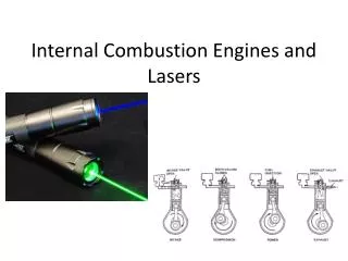
Unit - 2 INTERNAL COMBUSTION ENGINES
IC ENGINES Introduction Internal combustion engine External combustion engine Classification of internal combustion engines Parts of internal combustion engine Working of four stroke petrol engine Working of four stroke diesel engine Two stroke petrol engine. Two stroke diesel engine
INTRODUCTION Any machine, which converts heat energy in to useful mechanical energy, is known as an engine. The machines may be a gas turbine, steam turbine, I c engine All the engines comes under two classifications, they are i) Internal combustion engine ii) External combustion engine
Internal combustion engine: If the combustion of fuel takes in a cylinder and the heat is converted in to mechanical energy, is known as internal combustion engine, Ex Engines of moped, scooter, bikes, cars, bus, trucks etc; External combustion engine: If the combustion of fuel takes place in a combustion chamber and the heat energy is taken to a machine through pipe line there the heat energy is converted in to mechanical energy is known as external combustion engines. Ex, gas turbine and steam engine INTRODUCTION
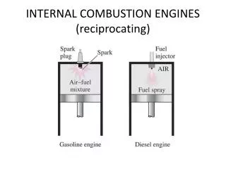
CLASSIFICATION OF INTERNAL COMBUSTION ENGINES Internal combustion engines are classified according to 1) According to thermodynamic cycle i) Otto cycle ii) Diesel cycle iii) Dual combustion cycle 2) According to number of strokes i) Two stroke ii) Four stroke 3) According to number of cylinders i) Single cylinder engine ii) Multi cylinder engine 4) According to method of ignition i) Spark ignition (petrol) ii) Compression ignition (diesel)
CLASSIFICATION OF INTERNAL COMBUSTION ENGINES 5) According to type of fuel used i) Petrol ii) Diesel iii) Gas iv) Bio fuel 6) According to position of cylinder i) Horizontal engine ii) Vertical engine (car, bus, truck engines) iii) Vee engine v) Opposed cylinder engine 7) According to method of cooling i) Air cooling ii) Water cooling iii) Liquid cooling 8) According to speed of engine i) Slow speed engine ii) Medium speed engine iii) High speed engine
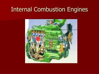
PARTS OF INTERNAL COMBUSTION ENGINE Cylinder, Head, piston, piston rings connecting rod and crankshaft.
IC Engine Technology: Bore: The inside diameter of the engine cylinder is termed as Bore. Stroke: It is the linear distance, measured parallel to the axis of the cylinder, between extreme upper and lower positions of the piston. Top Dead Centre (TDC): TDC in vertical engine is the extreme position of the piston on the top of the cylinder (head side). The cylinder volume is at a minimum. In case of horizontal engine this position is known as inner dead center (IDC).
IC Engine Technology: Bottom Dead Centre (BDC): BDC in vertical engine is the extreme position of the piston on the bottom of the cylinder. The cylinder volume will be maximum. In case of horizontal engine, this position is known as outer dead center (ODC). Compression ratio: It is the ratio of the volume when the piston is at BDC to the volume when the piston at TDC. Compression ratio = Maximum cylinder volume / minimum cylinder volume. R = V/Vc Cylinder volume.
IC Engine Technology: Piston Area (A) It is the cross sectional area of the cylinder. Displacement Volume/Swept volume (Vs): Volume covered by the piston between TDC & BDC. It is also called as stroke volume. Vs = A L Clearance volume (Vc): Volume on the combustion side of the piston at TDC Cylinder volume (V): V = Vs+Vc
4 Stroke petrol engine • Structure • Cylinder • Mechanically operated valves • Inlet valves • Exhaust valves • Spark plug • Connecting rod • Crank • Crank shaft
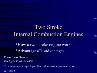
4 Strokes are Suction stroke Compression stroke Power stroke Exhaust stroke Works on the principle of Otto cycle
Suction stroke The inlet valve (I) opens and air fuel mixture (charge) is sucked into the cylinder. The piston moves downwards from top dead center (TDC) till it reaches bottom dead center (BDC). During suction stroke exhaust valve (E) is closed. Due to the suction created by the downward motion of the piston, inside of the cylinder pressure becomes slightly less than atmosphere. Due to the pressure deferential, fresh charge will enter into the cylinder.
Compression stroke During compression stroke both inlet and exhaust valves are closed. In this stroke the piston travels from BDC to TDC. When the piston starts moving from BDC to TDC the mixture is compressed, and the pressure increases in the cylinder. The line BC represents the compression stroke.
Compression stroke Before the end of the compression stroke, the spark occurs, this spark ignites the petrol and air mix. The combustion of mixture releases hot gases, which will increase pressure at constant volume. The line CD represents increase in the pressure at constant volume.
Power stroke: During power stroke (expansion stroke) both inlet valve and exhaust valve are in closed position. The high-pressure gases produced due to combustion, will exert pressure on the top face of the piston, the piston moves rapidly in the down ward direction performs power stroke.
Exhaust stroke: At the beginning of exhaust stroke, the exhaust valve opens, and the upward movement of the piston pushes the exhaust gases out the cylinder. At the end of the exhaust stroke the exhaust valve closes.
Starting position Compression stroke Suction stroke Power stroke Expansion stroke Ignition
Cylinder, Piston, Head, Crankcase, Connecting rod, Crankshaft, Fuel injector, Inlet and exhaust valve. The parts of four-stroke diesel engine Works on the principle of diesel cycle
Four strokes are The piston performs four strokes to complete one cycle. The four different strokes are i) Suction stroke ii) Compression stroke iii) Power or Expansion stroke iv) Exhaust stroke.
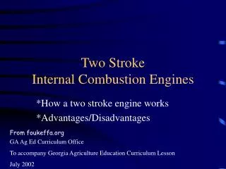
2 Stroke petrol engine Structure Cylinder Transfer port Inlet port Exhaust port Spark plug Connecting rod Crank Crank shaft Crank case
2 Stroke petrol engine One cycle is completed in 2 strokes of the piston (in one revolution of the crankshaft). It has only ports at the cylinder walls and has no valves. {Suction + compression }---- 1st stroke {power + exhaust } ----- 2nd stroke Scavenging: The exhaust gases are removed from the cylinder with the help of fresh compressed charge. This process of removing exhaust gases is called scavenging.
2 Stroke petrol engine 1. Inlet Port: Through this inlet port only, Fresh charge from the carburetor is taken into the cylinder. 2. Transfer port: Through this Transfer port only, fresh charge from the bottom of the piston is supplied to the cylinder. 3. Exhaust port: The Hot exhaust gases are pushed out from the combustion chamber. The cycle beginning at the point when the piston reaches TDC at the end of the compression stroke.
2 Stroke petrol engine Intake. The fuel/air mixture is first drawn into the crankcase by the vacuum created during the upward stroke of the piston.
During the downward stroke the fuel mixture is compressed in the crankcase.
Compression. The piston then rises, driven by flywheel momentum, and compresses the fuel mixture. (At the same time, another intake stroke is happening beneath the piston).
Power. At the top of the stroke the spark plug ignites the fuel mixture. The burning fuel expands, driving the piston downward, to complete the cycle.
Transfer/Exhaust. Toward the end of the stroke, the piston exposes the intake port, allowing the compressed fuel/air mixture in the crankcase to escape around the piston into the main cylinder. This expels the exhaust gasses out the exhaust port, usually located on the opposite side of the cylinder. Unfortunately, some of the fresh fuel mixture is usually expelled as well.
Mean effective pressure Is defined as the avg presure acting on the piston which will produce the same output As is done by the varying pressure during cycle. Area of indicator loop = area of rect. mep(Pm) = work done/ swept volume = area od indicator loop/ Vs
Indicated power of a 4stroke engine Work produced / stroke or / cycle = mean force acting on piston X piston displacement = Pm x A x L Work produced / min = (Work produced by piston/cycle) x (number of cycles/ min) = (Pm x A x L) x n In 4 stoke IC engine, 1 cycle will be completed in 2 revolutions of crank shaft. The work will be produced in every alternate revolution of the crank shaft ,thus Number of cycles / min will be equal to half the number of revolutions / min
N = N/2 Work produced by the piston = Pm x L x A x (N/2) Indicated power = (Pm x L x A x (N/2)) /60 W Indicated power in 2 stroke Work produced by the piston = Pm x L x A x N Indicated power = (Pm x L x A x N) /60 W