Download

1 / 31
310 likes | 447 Views
A Single-Channel Solution for Transmission Power Control in Wireless Ad Hoc Networks. Alaa Muqattash and Marwan Krunz University of Arizon MobiHoc 2004 Presenter :gigigi. Outline. Introduction Motivation Power control MAC protocol (POWMAC) Detail Simulation environment and results

E N D
A Single-Channel Solution for Transmission Power Controlin Wireless Ad Hoc Networks Alaa Muqattash and Marwan Krunz University of Arizon MobiHoc 2004 Presenter :gigigi
Outline • Introduction • Motivation • Power control MAC protocol (POWMAC) • Detail • Simulation environment and results • Conclusions
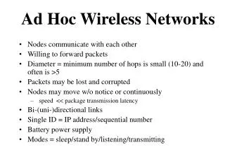
Introduction - IEEE 802.11 D C F E B A
Motivation - Power Control D C F E B A
POWMAC – RTS(MAX) D C F E B A
POWMAC – CTS (adjustable) D C F E B A
POWMAC – DTS(MAX) D C F E B A
POWMAC – Access Window D C F E B A
POWMAC - DATA(adjustable) D C F E B A
POWMAC - ACK (adjustable) D C F E B A
Details • The maximum tolerable interference (MTI) of node u, denoted by • Channel gain Gi ubetween nodes i andu
Details - RTS • the maximum allowable TP that node i can use without disturbing any of its neighbors
Details - ACK • FEC code • the same power level that would have been used if i were to send a data packet to j.
Simulation environment - Random Grid • 16 mobile nodes • square area of length 1500 meters. • The square is split into 16 smaller squares
Simulation environment - Clustered • 600 × 600 • split into 4 equal groups, each occupying a 100 × 100 square in one of the corners of the complete area
Conclusion • Single transceiver and single channel • Improve the network throughput by up to 45% in random grid topologies and much more than that in clustered topologies.