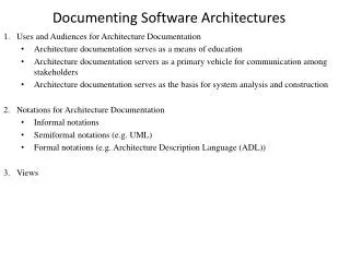
Documenting a Software Architecture
460 likes | 495 Views
Learn the importance of documenting software architecture, including key views, reasons, and challenges involved. Discover why documenting architectures is essential for effective communication and system development. Utilize UML 2.0 for structured documentation.

Documenting a Software Architecture
E N D
Presentation Transcript
Engr. M. Fahad KhanLecturer Software Engineering DepartmentUniversity Of Engineering & Technology Taxila
Documenting a Software Architecture Ref: Chapter 06 Essential Software Engineering By Ian Gortan
Importance of Documenting an architecture • The key to communicating to stakeholders the blueprint of the system you are building is to document the software architecture. • Software architectures are represented through different views—functional, operational, decisional, and so on. • No single view can represent the entire architecture. • Not all views are required to represent the architecture of a system for a specific enterprise or problem domain.
Importance of Documenting an architecture The architect determines the set of views that adequately represent the required dimensions of the software architecture.
Importance of Documenting an architecture By documenting the different views and capturing the development of each part, you can communicate information about the evolving system to the development team and to the business and IT stakeholders.
Importance of Documenting an architecture A software architecture has a set of business and engineering goals that it is expected to meet. Documentation of the architecture communicates to the stakeholders how these goals will be achieved. Experience tells us that documenting architectures is not a simple job.
Reasons for Documenting an architecture There are many other good reasons why we want to document our architectures, for example: • Others can understand and evaluate the design. This includes any of the application stakeholders, but most commonly other members of the design and development team. • We can understand the design when we return to it after a period of time.
Reasons for Documenting an architecture • Others in the project team and development organization can learn from the architecture by digesting the thinking behind the design. • We can do analysis on the design, perhaps to assess its likely performance, or to generate standard metrics like coupling and cohesion.
Documenting architectures is problematic because • There’s no universally accepted architecture documentation standard. • An architecture can be complex, and documenting it in a comprehensible manner is time consuming and non-trivial. • An architecture has many possible views. Documenting all the potentially useful ones is time consuming and expensive.
Documenting architectures is problematic because An architecture design often evolves as the system is incrementally developed and more insights into the problem domain are gained. Keeping the architecture documents current is often an overlooked activity, especially with time and schedule pressures in a project.
What to Document In a small team, interpersonal communication is often good, so that the documentation can be minimal, and maybe even maintained on a whiteboard or two.
What to Document • In larger teams, and especially when groups are not co-located in the same offices or building, the architecture documentation becomes of vital importance for describing design elements such as: • Component interfaces • Subsystems constraints • Test scenarios • third party component purchasing decisions • Team structure and schedule dependencies • External services to be offered by the application.
UML 2.0 • UML has become the predominant software description language that is used across the whole range of software development domains. • It has wide and now quality and low-cost tool support, and hence is easily accessible and useable for software architects, designers, developers, students – everyone in fact.
UML 2.0 • UML 2.0 is a major upgrade of the modeling language. • It adds several new features and, significantly, it formalizes many aspects of the language.
UML 2.0 • This formalization helps in two ways. • For designers, it eliminates ambiguity from the models, helping to increase comprehensibility. • Second, it supports the goal of model-driven development, in which UML models are used for code generation. The UML 2.0 modeling notations cover both structural and behavioral aspects of software systems.
Structural Diagrams The structure diagrams define the static architecture of a model, and specifically are: • Class diagrams: Show the classes in the system and their relationships. • Component diagrams: Describe the relationship between components with well-defined interfaces. Components typically comprise multiple classes. • Package diagrams: Divide the model into groups of elements and describe the dependencies between them at a high level.
Structural Diagrams • Deployment diagrams: Show how components and other software artifacts like processes are distributed to physical hardware. • Object diagrams: Depict how objects are related and used at run-time. These are often called instance diagrams. • Composite Structure diagrams: Show the internal structure of classes or components in terms of their composed objects and their relationships.
Behavior Diagrams Behavior diagrams show the interactions and state changes that occur as elements in the model execute: • Activity diagrams: Similar to flow charts, and used for defining program logic and business processes. • Communication diagrams: Called collaboration diagrams in UML 1.x, they depict the sequence of calls between objects at run-time. • Sequence diagrams: Often called swim-lane diagrams after their vertical timelines, they show the sequence of messages exchanged between objects.
Behavior Diagrams • State Machine diagrams: Describe the internals of an object, showing its states and events, and conditions that cause state transitions. • Interaction Overview diagrams: These are similar to activity diagrams, but can include other UML interaction diagrams as well as activities. They are intended to show control flow across a number of simpler scenarios.
Structural Diagrams • Timing diagrams: These essentially combine sequence and state diagrams to describe an object's various states over time and the messages that alter the object’s state. • Use Case diagrams: These capture interactions between the system and its environment, including users and other systems.
Informal description of architecture using Simple box-and-arrow Notation
The internal structure of the most complex of these, Order Processing. It includes a class essentially to encapsulate each interaction with an existing system. Classes for the order processing component
Sequence Diagram With this level of description, we can now create a sequence diagram showing the main interactions between the architectural elements.
Sequence Diagram Sequence diagrams are probably the most useful technique in the UML for modeling the behavior of the components in an architecture.
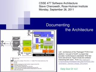
UML Deployment Diagram • Next UML deployment diagram is created that shows where the various components will execute. • This is because many of the components in the design already exist, and the architect must show how the new components interact with these in the deployment environment.
UML Deployment Diagram • The figure shown allocates components to servers and shows the dependencies between the components. • It’s often useful to label the dependencies with a name that indicates the protocol that is used to communicate between the components. • For example, the Order Processing executable component requires JDBC28 to access the New Orders table in the Orders DB database.
More on Component Diagrams • Component diagrams are very useful for sketching out the structure of an application architecture. • They clearly depict the major parts of the system, and can show which off-the-shelf technologies will be used as well as the new components that need to be built.
Component Interfaces • UML 2.0 has also introduced improved notations for representing component interfaces. • An interface is a collection of methods that a component supports. • In addition to the UML 1.x “lollipop” notation for representing an interface supported by a component (a “provided” interface), the ‘socket’ notation can be used to specify that a component needs a particular interface to be supported by its environment(a “required” interface).
Component Interfaces • By connecting provided and required interfaces, components can be “plugged” or “wired” together as shown in next slide. • The provided interfaces are named, and capture the dependencies between components. Interface names should correspond to those used by off-the-shelf applications in use, or existing home-grown component interfaces.
Ports • UML 2.0 makes it possible to refine interface definitions even further, and depict how they are supported within the context of a component. This is done by associating interfaces with ‘ports’. • Ports define a unique, optionally named interaction point between a component and its external environment. • They are represented by small squares on the edge of the component, and have one or more provides or requires interfaces associated with them.
Components • UML 2.0 composite diagrams enable us to show the internal structure of a design element such as a component. • The next diagram shows that we can explicitly depict which objects comprise the component implementation, and how they are related to each other and to the ports the component supports.
Parts • The internal objects are represented by UML 2.0 “parts”. Parts are defined in UML 2.0 as run-time instances of classes that are owned by the containing class or component. • Parts are linked by connectors and describe configurations of instances that are created within an instance of the containing component/class.
Architecture Documentation Template • It’s always useful for an organization to have a document template available for capturing project specific documentation. • Templates reduce the start-up time for projects by providing ready-made document structures for project members to use. • Templates also help with the training of new staff as they tell developers what issues the organization requires them to consider and think about in the production of their system.
Figure shows the headings structure for a documentation template that can be used for capturing an architecture design.
Key Points to remember • Generating architecture documentation is nearly always a good idea. • The trick is to spend just enough effort to produce only documentation that will be useful for the project’s various stakeholders. • The UML, especially with version 2.0, makes it pretty straightforward to document various structural and behavioral views of a design.
If you have any query please feel free to ask Phone: +92-51-9047-574 Fax: +92-51-9047-420 Email:fahad@uettaxila.edu.pk University Of Engineering & Technology Taxila Pakistan