MAGNET MAPPING
330 likes | 346 Views
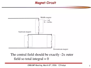
MAGNET MAPPING. J. Cobb V. Blackmore (not responsible for the content of this talk). THE GOALS. Find the magnetic axes of the magnets Align magnetic axes of modules to beam axis Ideally to better than 0.5 mm Check fields agree with calculated fields and / or

MAGNET MAPPING
E N D
Presentation Transcript
MAGNET MAPPING J. Cobb V. Blackmore (not responsible for the content of this talk)
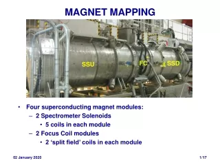
THE GOALS • Find the magnetic axes of the magnets • Align magnetic axes of modules to beam axis • Ideally to better than 0.5 mm • Check fields agree with calculated fields • and / or • Find effective conductor dimensions • Almost finished finding axes • Final checks still to make • Have made first pass at as-is alignment in Hall
THE SCOPE • Initially the two Focus Coils • Include the two Spectrometer Solenoids • Four magnets • Eight surveys (at least) • Including surveys in Hall • All magnets & mappings subtly different • Not trivial – not impossible – to write general purpose code • Enough meat for at least two D. Phil. theses
THE MAPPER Seven 3-axis Hall probes at r = 0 … 180 mm Disc rotates Mainly use probe 1 at r = 30 mm
THE DATA • All four modules mapped • FCs in R9 • SSU & SSD at manufacturers • Longitudinal (z) scan at fixed angle of disc (f ) • dz = 10, 20, 40 mm • Change f and repeat • f increments from 5, 20, 45 degrees • A number of different currents • With/without VP for the SSs • Huge amount of data • Much not looked at
THE ASSUMPTIONS • Mapper mechanics are perfect: • Mapper disc: • Perpendicular to longitudinal axis of movement (z) • Rotates around longitudinal axis • Hall probes • z axes parallel to mapper z axis • x (or y) axes radial from mapper z axis • Mapper position stable (i.e. not kicked!)
THE TRANSFORMATIONS • Mapper measures • Br and Bf at (r,f) in disc system • Rotate coordinates & field components to get: • (x,y) and Bx, By in mapper system • Br and Bf aren’t true radial & azimuthal field components because mapper axis is not magnetic axis – can be confusing • Apply survey corrections to x and y
THE SURVEY CORRECTIONS FC2 • Mapper disc doesn’t move in straight line • Transverse movement surveyed for each module • < 0.6 mm for FCs • ~ 2 – 3 mm for SSU & SSD • Survey corrections applied to x and y coordinates • Not applied to field components (yet) • Should we? • Imply pitch & yaw of mapper disc?
AXIS FINDING • Considered, briefly, global fit to measured fields: • Models of conductors • Rotations • Global c2 • But too awful to contemplate for very long • Too many parameters • Too slow to calculate fields &c. • Use model-independent method to find axis • No field calculations required
AXIS FINDING 1 • Magnetic axis Bperp = 0 • Cylindrical symmetry assumed • Maxwell-Gauss: • Expect Bx and By to be linear in x or y and zero on axis
SOME FIELDS • Same scale for Bx and Bz • 8 (x,y) points at each z • Information about axis mainly from where Bz changing fast
AXIS FINDING 2 • Expect Bx and By to be linear in x or y close to axis • zero on axis • Sounds simple enough • But • Bx and By are small ( < 1500 gauss) close to axis • Bz can be large (2kG – 40kG) • Allow for components of Bz in (mapper) Bx, By due to inclination – up to a few mr – of axis in mapper system
AXIS FINDING 3 To first order, measured Bx at fixed z is a = angle of magnetic axis in x – z plane, p is intercept Angles are small and can work in projections
AXIS FINDING 4 From previous slide
UNEXPECTED BEHAVIOUR • Bx (By) versus x (y) for full rotation of probe 1 at two zs in FC1 • 8 (x,y) from phi = 0, 45, 90 … degrees • Why loops? • Look at transverse field vectors, (Bx,By)
FIELD HAS A CURL ? • Transverse field vectors • Should converge to a point: the axis • Measured field seems to have non-zero curl • Ad hoc correction…
CURL CORRECTION 1 If no current enclosed Measured fields of each probe corrected by mean Bf at each z
CURL CORRECTION 2 Probes 1,2 & 3 Sum over 8 phi (0 – 315 degrees) Bz Each probe has different correction Can amount to 70 – 80 gauss Attributable to one axis of probe not truly radial (by ~ 1 degree)
CURL CORRECTION 3 • Seems to work • but needs revisiting Before After
THE FITS AND AFTER • Most of the fits done by VB • Similar to above outline • Different in detail • Include • Mapper surveys • Curl corrections • Have my own simple ‘Poor Man’s Fit’ • Works for FCs only • Useful reality check • Residuals suggest that errors dominated by systematics • Parallel working / checking has been very useful • Find mistakes (mainly mine) • Still work in progress • Decide ~ Easter to make first pass to see where we are globally
SOME AXIS FIT RESIDUALS Horizontal Vertical FC1 Flip Mode
THE GLOBAL PICTURE • Looked – first pass – to see how magnetic axes would line up • i.e. how magnetic axes relate to flanges on modules • In all cases mapper axis was aligned to bore tube • Doesn’t immediately relate to flanges &c. • Had to understand external surveys • Given in weird R9 coordinates for FC1 and FC2 • FC2 re-surveyed • Simpler for SSD and SSU • Axes of SSU and FC2 seemed to be within ~ 0.5 – 1mm of centres of flanges • SSD axis ~ 4 mm off at upstream end; ~ 10 mm off at DS end • Is this right?
SSD MAPPER SURVEY x – z + 3mm upstream end to -1 mm downstream y – z +2.5 upstream end to -1 mm downstream
FIRST PASS AXES in HALL (as of 27/III/15) • Assumes modules bolted exactlyflange-centre to flange centre • Assumes SS bore tubes perpendicular to flanges Plan Elevation
HOW CAN WE CHECK SSD AXIS? • Check what we did (obviously) • FC bobbin axes aligned to < 100 microns to flange centres • Our only ‘calibration’ • Fits should be good to roughly that level • But some ambiguities with FC2 mapper survey • Work in progress • Shall say no more about FC2 • FC1 looked OK – but must revisit • Invent different methods to find axis: • Peak finding (VB) • Field vectors (JC)
PEAK FINDING • Btotal must be maximum or minimum on the axis • Needs fitting 2D function B(x,y) at fixed z & good relative calibration of probes • Not so useful
VECTOR PLOTS Upstream Downstream • Draw transverse field vectors from probe positions • Uses all the probes independently • Vectors should intersect at the magnetic axis • Survey corrections (2 – 3 mm upstream end) can be applied afterwards • Result seems unambiguous & confirms fits
IN THE HALL • Assume: • We trust the results of the mapping • Some details still to be understood • We understand the surveys • Ditto • We trust the surveyors • Add the real Hall survey of modules • How do the axes align in real life? • Ambiguous as to whether FC2 survey was before or after bolting modules together
FC magnetic axis not shown; will be close (~0.5mm) to flange centre axis Magnetic axis Magnetic axis
8.5 mm Magnetic axis Magnetic axis
SUMMARY • Simultaneous mapping of four modules is bit of a nightmare • All dead-reckoning / no real calibration • Learnt ~ as much about the mapper as the modules • As far as we can tell • Axis of SSD is out of spec. • As far as I can tell • Modules not well-aligned in the Hall • Haven’t yet had opportunity to look at fields • Comparison with nominal dimensions • (know there’s a ~1.5% discrepancy for FCs) • TBC