Download
1 / 21
210 likes | 236 Views
Detailed overview of mapping the Hall B tagger magnet using Ziptrack apparatus, operation, alignment methods, and field analysis. Comparison to Hall D mapping process and scenarios for efficient mapping strategies considering accuracy requirements.

E N D
Some thoughts on Hall D tagger magnet field mapping D. Sober Catholic University of America GlueX Beam/Tagger biweekly meeting 23 July 2012 D. Sober
Contents • Mapping of the Hall B tagger magnet • What we need for Hall D • How to do it D. Sober
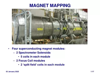
Hall B tagger magnet • Comparable in size to Hall D 6.3 m x 0.5 m x 5.7 cm gap • No TOSCA calculations • Initially no pair spectrometer planned – tagger field map → tagger energy scale So full field map (gap and fringe field) was necessary D. Sober
Hall B tagger field mapping Ziptrack apparatus borrowed from Fermilab in 1993 Upgraded apparatus at Fermilab (2007) – not available for loan D. Sober
Ziptrack modification for Hall B 3-axis Hall probe attached to long arm which fit inside 6.2 cm magnet gap magnet D. Sober
Operation of Ziptrack • Long beam moves in y-direction (vertical) • Towers move in x-direction (toward/away) • Probe carriage moves in z-direction (length of long beam, > 6 m) with string drive at ≈1 inch/sec, readings taken “on the fly” • Data acquisition (1993 version) PC controlled, files written to hard disk and 1.4 MB diskettes (no network in halls) • Quality of data checked in near-real time using PC on neighboring table. D. Sober
Hall B tagger mapping • June 13-29 and Sept. 3-4, 17-19, 1993 • Lots of learning experience with power supply, cooling water, … • Ziptrack Hall probes were calibrated against NMR probe inserted at fixed position. • Took full map (gap and fringe field, 1.0” x 0.5” grid, y midplane only) at 10 magnet currents, corresponding to E0= 0.4 - 6.2 GeV. • Fringe field mapped to ≈16” (>6 gap widths.) Some data taken above and below midplane in fringe field region (not useful) • Entry and full-energy exit regions were mapped separately “by hand” at each current D. Sober
Fixing the map coordinate system • The upper and lower poles each had a ≈3 mm alignment hole on the symmetry plane located in the uniform-B region • Before each set of Ziptrack passes, an alignment pin (aluminum with steel insert, according to log book) was inserted into the lower pole, and a set of scans with fine steps in x and z was taken in order to determine (manually) the zero position. D. Sober
Alignment pin scans No difficulty in locating pin to 0.01” = 0.25 mm D. Sober
Hall B tagger contour maps(Nucl. Instr. Meth. A 440, 263 (2000)) D. Sober
Detailed contour map D. Sober
Detailed contour maps D. Sober
Analysis of field maps • Only the principal field component was analyzed • Main field region converted to a uniform 1” x 0.5” grid covering all possible trajectories between the poles and to ≈16” (6 gap widths) of fringe field • Entry and full-energy exit fields were stored in separate grids in their own coordinate systems • Ray-tracing using SNAKE code obtained from Hall A. SNAKE easily accommodates overlapping “field boxes” with transition at specified surface. D. Sober
What is different in Hall D? • We will have TOSCA field maps, but … • Physical mapping is necessary to check the TOSCA modeling • We will not have a Ziptrack-like device D. Sober
What will it take to produce a full map? Including the full-energy electron, nearly the entire pole area is important. If we want precision only for the microscope and endpoint regions, only ≈ half of the pole area need be mapped. D. Sober
Possible mapping scenario • Best case: parasite on someone’s automated or semi-automated system (other halls?) • Worst case: go it alone, with precision Hall probe and x-z translation stages with ≈1 m range of motion • No need to measure out of midplane - probe arm may slide on lower pole face (possible difficulties with alignment pin and with fixed NMR probe) • Alignment pins: should have 2 pins within range of translation stage, e.g. 80 cm apart (7-8 pins) D. Sober
Possible mapping scenario (continued) Time required, using a non-automated system: Assume 2 points per minute = 120 / hour • Map entire pole plus 15 cm (5 gap widths) of fringe field at 1” x 1” at 1” x ½” 4500 points (38 hr) 9000 (76 hr) • Map only microscope-to-endpoint region plus fringe field 1850 (16 hr) 3700 (32 hr) None of these is beyond the realm of possibility. D. Sober
Possible mapping scenario (continued) • One full map (including entry and full-energy exit regions) at nominal field should be sufficient … if there are no major discrepancies with TOSCA map • Are we interested in other field settings? If we change our mind later, it will be too late for mapping. A minimal map (x sweep from center to fringe region at a few z values) should be performed at several currents. D. Sober
Effect of vacuum on magnet field • Mapping must be performed in air • Vacuum will cause gap to narrow slightly • In first order, this effect is canceled out by requiring that the full-energy electron deflection hits the beam dump at the right place (one obtains the correct B field at slightly lower current) – this is one good reason to map the field over the entire full-energy orbit • If we can calculate (or measure) the change in gap, TOSCA can give the field both ways and allow us to correct the measured field map. D. Sober
Some conclusions • Even with TOSCA calculations, we need to do at least a limited field map • Region around field boundary is critical for precise energy calculations → Field map coordinate system must be accurately fixed • Multiple alignment holes useful because of likely limited range of mapper translation. They should be in both poles (so that probe arm can slide on lower pole face), and also near entry and full-energy exit edges D. Sober
Some homework (maybe someone knows the answers already) • Find what mapping equipment is available in other halls (and for solenoid) • Where will the fixed NMR probe be located? If it is in a no-beam corner of the magnet, then there is no difficulty mapping around it; otherwise needs some thought. • Who is calculating field maps with TOSCA? D. Sober