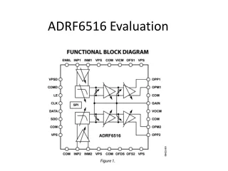
ADRF6516 Evaluation
160 likes | 192 Views
This evaluation explores the powering and programming requirements of the ADRF6516 board, including the hierarchy, gain select options, and testing results. It also discusses saturation and error sources, and suggests possible next steps for further testing.

ADRF6516 Evaluation
E N D
Presentation Transcript
ADRF6516 Evaluation David Hann
Powering the Board • VPOS = 3.3 V PS • COM -> Com PS • VPOSD/COMD - device’s power
ADRF Software • Board Must Be Powered • Board Must Be Programmed Each Start Up • Board Does Not Require a Computer After Programming • Hierarchy: Filter, Pre-Amp, Post-Amp, VGA Max • Gain Select Options are each a Binary Choice Testing: • Low Settings: 3+6+22 = 31 dB, 31 MHz • High Settings: 6+12+28 = 46 dB, 31 MHz • Plots are at High Settings unless otherwise noted
Saturation at 20 MHz Vin = 20 mV pk-pk, 20 MHz VGAIN = 980 mV ADRF = High Settings
Typical Saturation Vin = 20 mV pk-pk, 5 MHz VGAIN = 990 mV ADRF = High Settings
3.7 dB Error Source • Fairly Consistent (σ=.44) • 200 mV error in VGAIN to replicate • Not From Internal Inductance
Shelf Gain (dB) • 5 MHz: 43.9 dB • 10 MHz: 43.5 dB • 15 MHz: 43.6 dB • 20 MHz: 43.9 dB • Data Sheet: 46 dB
Possible Next Steps • DC Decoupling Testing • Corner Frequency Testing