PDR slides for Tomo Sugano
240 likes | 490 Views
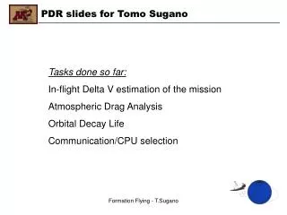
PDR slides for Tomo Sugano. Tasks done so far: In-flight Delta V estimation of the mission Atmospheric Drag Analysis Orbital Decay Life Communication/CPU selection. Presence of Atmospheric Drag in LEO orbit. Atmospheric density is largest at perigee Largest drag is experienced at perigee

PDR slides for Tomo Sugano
E N D
Presentation Transcript
PDR slides for Tomo Sugano Tasks done so far: In-flight Delta V estimation of the mission Atmospheric Drag Analysis Orbital Decay Life Communication/CPU selection Formation Flying - T.Sugano
Presence of Atmospheric Drag in LEO orbit • Atmospheric density is largest at perigee • Largest drag is experienced at perigee • Atmospheric drag shall be considered if orbit perigee height is <1000 km • Atmospheric drag acceleration (D): 1/(ACD/m) is the ballistic coefficient, a measure of resistance to fluid A (projected area normal to flight path) m (mass of spacecraft) f (latitude correction coefficient) Formation Flying - T.Sugano
Effect of Atmospheric Drag to Orbit Profile • Atmospheric drag tends to circularise the probe’s orbit • Drag effect greatest at perigee • Apogee height consequently reduced • Overall altitude is lost unless orbit correction is done • Determinant of satellite decay time Formation Flying - T.Sugano
Drag Coefficient of STS and other LEO probes • STS Orbiter (aka the Space Shuttle) • STS has a CD of 2.0 at typical mission altitudes in LEO • Above 200 km of orbit altitude, use 2.2 < CD < 3.0 • Cylindrical probes have larger CD than those of spherical probes • Exact CD is hard to predict as LEO environment is not fully understood • Currently best determined by actual flight test Formation Flying - T.Sugano
Consideration of Drag in Formation Flying • FF mission is required to last at least 24 hours • STS orbiter (primary) typically performs a trim burn once a day • Trim burns correct orbit altitude and ascending node • Drag differentials present between primary and satellite(s) • Possible consideration of LEO drag in our mission Formation Flying - T.Sugano
Orbital Decay • Perturbation in LEO is mainly due to atmospheric drag • Orbital decay of space probes (e.g. Space Shuttle, ISS, satellites) • Altitude correction “trim burns” necessary to keep probes in orbit • Orbit will decay in the absence of trim burns Formation Flying - T.Sugano
Orbit Lifetime Estimation • Estimation of the orbit lifetime of our satellite after mission • Consider atmospheric drag effect only • Mission orbit is assumed virtually circular for simplicity Formation Flying - T.Sugano
Orbit Lifetime Equation • Circular Orbit Lifetime Equation (Approximation) a0 = initial altitude S = projected area of the space probe m = space probe mass Formation Flying - T.Sugano
Exponential Atmospheric Model • Scale height, H, obtained from tabulated data Formation Flying - T.Sugano
Assumptions set forth for our lifetime computation • Assumptions: (Made for worst case or shortest decay) m = 50 kg (maximum); S = 0.385m2 (spherical correction of max volume) CD = 3.0 (upper bound value in LEO probes) a0 = 6400 + 300 km (typical altitude for STS or ISS) Δ = 150 – 300 = - 150 km (typical re-entry altitude, note the minus sign) f = 1 (ignore latitude effect; not significant (<10%)) ρ0 = 2.418x10⁻¹¹ kg/m3 (Table, 300 km base altitude) • Unavoidable uncertainty Scale height, H - Not constant between orbit and re-entry altitude - Take H = 30 km, so β = 1 / (30 km) Formation Flying - T.Sugano
Computation Result • Based on the assumptions we made - T = tau_0 * 189.565 - T = (approx. 1.5 hr of initial orbit period)*(190) = 12 days • LEO Nanosat at 300 km of altitude will take 12 days to decay. Formation Flying - T.Sugano
Conclusion • Our Nanosat does not decease for 12 days • Retroburn delta-V input to decelerate the Nanosat for faster decay will be costly without a compelling space debris concern(?) • Unless allowed to dispose of the Nanosat in space, retrieval is rather recommended(?) • Retrieval may be attained fairly easily by using robot arm of STS perhaps equipped with capture net(?) Formation Flying - T.Sugano
Drag Differential Compensation • Different ballistic coefficients between the orbiter and the Nonosat • Consequent difference in drag forces exerted during mission • Ballistic Coeff. of STS >> Ballistic Coeff. of Nanosat • Nanosat must expend Delta-V to keep up with STS orbiter Formation Flying - T.Sugano
Computations • Atmospheric drag acceleration (Da): • Drag (acceleration) difference between the two spacecraft: STS: S = 64.1 m2, CD = 2.0, m = 104,000 kg (orbiter average) sat: S = 0.385 m2 (nominal), CD = 3.0 (worst case), m = 50 kg Formation Flying - T.Sugano
Computations (cont’d) • Orbiter speed (assuming circular orbit) • Definition of Delta-V (or specific impulse) • Mass expenditure of propellant (i.e. GN2 cold gas) Formation Flying - T.Sugano
Results • Using Isp = 65 sec; assume 50 kg for satellite weight • Conclusions - At the typical 300 km LEO, Delta-V for 1 day mission is 1.36 m/s - Satellite will need at least 107 grams of GN2 to compensate drag - Besides this Delta-V requirement, we have orbit transfer Delta-V (currently estimated at 1.17 m/s) and ADCS Delta-V. Formation Flying - T.Sugano
FCS and COMM • FCS – Flight Control System • COMM – Communications (camera is assumed to be part of COMM) • Satellite needs to handle both FCS and COMM systems • Use of COTS (Consumer Off-the-Shelf) computer(s) aimed • COMM utilizes a low-cost COTS transceiver radio Formation Flying - T.Sugano
CPU selection for the Nanosat • Arcom VIPER 400 MHz CPU recommended • VIPER is suitable because of its - Light weight, 96 grams - Operable temperature range, -40 C to + 85 C - Windows Embedded feature, easy to program - Computation speed, 400 MHz - Memory capacity, up to 64MB of SDRAM - Embedded audio I/O, necessary for COMM with voice radio • Redundancy can be implemented. Formation Flying - T.Sugano
Arcom VIPER 400 MHz embedded controller Formation Flying - T.Sugano
Radio selection for the Nanosat • Kenwood Free Talk XL 2W transceiver recommended • Kenwood Free Talk XL is suitable because of its - COTS nature, low cost - 2W of transmission power, more than enough for non-obstructed space communication, but higher wattage than FRS 500 mW radio - Ability to use both GMRS and FRS frequencies - FRS frequencies recommended because by international treaty FRS (Family walkie talkie) is restricted to 500 mW - 500 mW is too weak to penetrate into space - MilSpec cetified Formation Flying - T.Sugano
Kenwood Free Talk XL 2W FRS/GMRS Transceiver • 15 UHF channels (7 FRS and 8 GMRS) • 2W output for both categories • DC 7.2 V (600mAh) • Circuit board weighs only 60 grams • Speaker/Microphone/Encapsulation Removed Formation Flying - T.Sugano
Scheme of FCS/COMM Integration Formation Flying - T.Sugano
Detailed Scheme of integration Formation Flying - T.Sugano