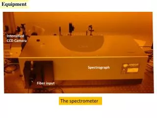
Spectrometer PDR
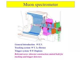
Spectrometer PDR. – The preliminary Design. John Ford (NRAO). Why a New Spectrometer?. Summary of Required Observing Modes. Overall Block Diagram. Analog System. Adapts output of Converter Modules to the ADC Low-pass filter Amplification Test tone injection Clock distribution

Spectrometer PDR
E N D
Presentation Transcript
Spectrometer PDR – The preliminary Design John Ford (NRAO)
Analog System • Adapts output of Converter Modules to the ADC • Low-pass filter • Amplification • Test tone injection • Clock distribution • Split and amplify clock signal • Distribute to all ROACH boards
Storage Subsystem • Project will supply ~100 TB of disk subsystems • Connected to 10 GbEthernet • Fast enough to support writing directly into subsystem for most observing (But not pulsar searching) • Data accessible for astronomers simultaneously with spectrometer use • Project will not supply • VAO integration • Archiving software or methodology • Long-term storage media
Preliminary Design Work • Developing support hardware • IF system interface • Anti-alias low-pass filters • Noise/test signal injection • Amplification • Analog to Digital Converter sampling clock generation/distribution • 1 Pulse Per Second distribution • Packaging
Preliminary Design Work • Concentrating on the hard parts • 3 GS/s sampling and PFB/FFT calculations • Heterogeneous Computing Approach • Divide processing into front/back ends • Use FPGAs to fully process bandwidths greater than 200 MHz • Use FPGA front-ends to pre-process, split and packetize data, then GPUs to provide fine channelization on narrower chunks • Software Design • Adapting concepts and code from the Green Bank Ultimate Pulsar Processing Instrument (GUPPI) • Adding support for the K-band FPA processing pipeline • Integrating with the GBT Monitor and Control System for user ease.