Download
1 / 26
280 likes | 405 Views
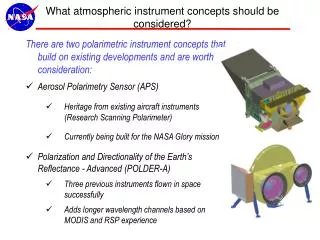
What atmospheric instrument concepts should be considered?. There are two polarimetric instrument concepts that build on existing developments and are worth consideration: Aerosol Polarimetry Sensor (APS) Heritage from existing aircraft instruments (Research Scanning Polarimeter)

E N D
What atmospheric instrument concepts should be considered? There are two polarimetric instrument concepts that build on existing developments and are worth consideration: • Aerosol Polarimetry Sensor (APS) • Heritage from existing aircraft instruments (Research Scanning Polarimeter) • Currently being built for the NASA Glory mission • Polarization and Directionality of the Earth’s Reflectance - Advanced (POLDER-A) • Three previous instruments flown in space successfully • Adds longer wavelength channels based on MODIS and RSP experience
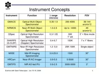
APS summary Type: Passive multi-angle photopolarimeter Fore-optic: Rotating polarization-compensated mirror assembly scanning along orbit-track +50.5° to –63° (fore-to-aft) from nadir Aft-optic: 6 bore-sighted optical assemblies, each with a Wollaston prism providing polarization separation, beamsplitters & bandpass filters producing spectral separation, and paired detectors sensing orthogonal polarizations Directionality: ~250 views of a scene Approx. dimensions:60 x 58 x 47 cm Mass/power/data rate:53 kg / 36 W / 120 kbps Spectral range: 412–2250 nm Measurement specifics:3 visible (412, 443, 555 nm), 3 near-IR (672, 865, 910 nm), and 3 short-wave IR (1378, 1610, 2250 nm) bands; three Stokes parameters (I, Q, and U) Ground resolution at nadir: 6 km SNR requirements:235 (channels 1 – 5, 8, and 9), 94 (channel 6), and 141 (channel 7) Polarization accuracy: 0.002 at P = 0.2, 0.003 at P = 0.5 Repeat cycle: 16 days APS angular scanning APS spectral channels
POLDER-A summary • Type: Passive multi-angle imaging photopolarimeter • Instrument concept:Wide field of view telecentric optics (separate for VIS and SWIR), rotating wheel with spectral and polarization filters, and 2-D detector arrays in the focal plane of the optics • Directionality: 15 views of a scene, ±55° from nadir • Cross-track swath: ±55° • Approx. dimensions:40 x 52 x 36 cm • Mass/power/data rate:30 kg / 30 W / 3 Mbps • Spectral range: 443–2130 nm • Measurement specifics: 2 visible (443, 490 nm), 2 near-IR (670, 865 nm), and 3 short-wave IR (1370, 1650, 2130 nm) bands; three Stokes parameters (I, Q, and U) in all channels except intensity-only channels 1 and 5. A UV band can be added. • Ground resolution at nadir: 4 km • SNR requirement:200 • Global coverage: 2 days
APS Functions in a Mission X • The APS is a high-precision multi-channel multi-angle photopolarimeter which will provide • benchmark aerosol and cloud retrievals along the satellite ground track; • continuation of the Glory APS climate record; • in-flight calibration of POLDER-A polarimetry and photometry; • improved and updated look-up tables for other instruments • Cost Estimate • Deleted • (Would be built in-house at GSFC, NRE costs covered by developing APS, existing MCT detectors owned by GSFC).
APS Calibration • APS has four calibration references: • Dark reference • Every scan (1.5 seconds) • Solar reference • Only illuminated weekly at passage over North pole by spacecraft maneuver • Unpolarized reference • Polarization scrambler • Every scan • Polarized reference • Crystal/wire grid polarizers • Every scan • The two polarimetric references are illuminated by Earth shine providing a continuous source of calibration over a wide dynamic range. • Approach already demonstrated accuracy of 0.1% for individual measurements over cloud decks.
APS Measurements • Polarization measurements are extremely sensitive to aerosol, size and complex refractive index. Variation as a function of angle and color provides discrimination: • Left hand figure shows fit between data and retrieval for low aerosol load (AOD=0.05, mr=1.43, reff=0.12 µm); • Right hand figure shows fit between data and retrieval for high aerosol load of smoke (AOD=1.1, mr=1.43, mi=0.06, reff=0.12 µm, layer top at 600 mbar, layer base > 850 mbar). • Retrievals are consistent with lidar (courtesy of Dennis Hlavka) for layering and TOMS AI (courtesy of Mike Fromm) for the imaginary refractive index given the layer height.
APS Measurements • Particle size distribution can be retrieved in the rainbow scattering angle range (Bréon and Goloub) using polarization and from reflectance measurements (Nakajima, King, Platnick). • Away from rainbow the cloud top height can be estimated from shorter wavelengths (410, 443, 470 nm). • In this angular range at longer wavelengths (865, 670, 555 nm) the optical depth, size and refractive index of accumulation mode particles can be determined. • Retrieved accumulation mode size of 0.15 µm is consistent with both CIMEL and AATS spectral extinction observations. The optical depth above cloud top from AATS is 0.2. Refractive index validation (1.52)????? • Cloud particle size distribution can be retrieved in the rainbow scattering angle range (Bréon and Goloub) using polarization and from reflectance measurements (Nakajima, King, Platnick, etc.).
APS Measurements • Polarized reflectance is sensitive to cloud top while the reflectance inabsorbing bands at 1590 nm and 2250 nm is sensitive to deeper layers. • Particle sizes retrieved using the two measurements are therefore indicative of profile variations in particle size.
APS Measurements • Profiles • NB: You cannot profile particle size using polarization + SWIR spectral bands + multi-angle measurements. • However: You can estimate parameterized profile properties e.g. assume linear liquid water path increase. Even if the assumed profile is wrong, but plausible (e.g. linear in surface area etc. other examples examined by Platnick) the estimate of LWP will still be better than a homogeneous assumption. • Cloud Pressure Thickness • Since polarized reflectance is generated at cloud top it is only affected by water vapor above cloud. • Reflectance depends on water above and in cloud. • Difference is water vapor within cloud (for single layer cloud over ocean). If you know the temperature and can assume water vapor mixing ratio is saturated then you can estimate the pressure thickness of the cloud => Nc. Existing tests good to ±10 mbar, but clouds are only 30-40 mbar thick.
POLDER-A functions in a Mission X • The POLDER-A is a multi-channel multi-angle imaging photopolarimeter which provides • detailed and accurate aerosol and cloud retrievals with a 2-day global coverage; • the requisite atmospheric correction for ocean color retrievals. • Cost Estimate • Deleted • (would be built by CNRS)
POLDER-A Measurements • The existing POLDER instruments provide multiple views of a given scene that allow the discrimination of small and large particles and accurate estimates of accumulation mode aerosol optical depths over urban and rural areas. • The advanced POLDER would add 1378 nm radiance and 1610/2250 nm I,Q and U measurements. Dust Pollution
Summary • APS and POLDER-A are instruments with considerable heritage and demonstrated performance that provide respectively: • Highly accurate aerosol and cloud properties along the satellite ground track • Broad spatial coverage with good quality atmospheric characterization • Our experience (for which we are grateful to Mike King) is that having an aircraft demonstration instrument is invaluable for algorithm development and understanding the available trade space for instrument design. • (e.g. only by looking at cloud observations for a wide range of cloud types was it clear that P960 < P865 always and the magnitude depends on cloud type - vertical extent)
Comments • You can do everything with a polarimeter (me) • You can do everything with a lidar (Hostetler, Muller, …) • You can do everything with a radar (Stephens, Ackerman, Heymsfield, …..) • Question: • What do you want to do? • How well do you need to do it? • What relative value do you put on each measurement? • Only when you answer these questions can you rationally discuss payloads.
APS Measurement Approach • How do you measure polarization? • Use a retarder and a polarizer. V is negligible for solar illumination and only a polarizer is needed to measure I, Q and U. El Detector Retarder, Polarizer, Stokes Vector
APS Measurement Approach • The differences required to calculate Q and U are differences between orthogonal polarization states, so if we measure these orthogonal states such that they are looking at the same scene at the same time we can effectively eliminate any “false” polarization. • This can be done very simply using a Wollaston prism in the collimated beam of a relay telescope. Wollaston prism - splits beam into orthogonal polarizations Objective Field Stop Collimator Dichroics
APS Measurement Approach • Using dichroic beam splitters you can make measurements for multiple spectral bands in a single telescope (3 in the case of APS). • Use one telescope for Q and one telescope for U. • If we are measuring a total of 9 bands this means we need 3 telescopes for Q and 3 telescopes for U for a total of 6 telescopes.
APS Measurement Approach • We can make telescopes that will measure polarization accurately. Now we need to point them at things (the earth) without losing the polarimetric accuracy they provide. • Crossed mirrors, if identical, introduce no polarization into the scene polarized radiance and allow the telescope fields of view to be scanned across the earth either across track like MODIS, or along track as is planned for APS. • One polarization experiences an s, then a type p reflection, while the other experiences a p then an s type reflection. Polarization induced by the scan mirror assembly of an aircraft precursor (the Research Scanning Polarimeter) to APS was not measurable <<0.1%. RSP mirror alignment Scanner uses matched mirrors illuminated at 45° with reflection planes at 90° to one another
APS Radiometric Calibration • Radiometric • Use space-grade spectralon diffuser with one-time deployable cover to provide reflectance based calibration scale at insertion. • Solar calibration is performed when the spaceraft is in the penumbra after passage over the North pole. • Spacecraft performs a 29° yaw for the solar diffuser to be optimally illuminated (maximise direct illumination, minimize reflected illumination).
APS Radiometric Calibration • Radiometric • Since diffusers degrade over time lunar calibration needs to be used to track stability of calibration coefficients. • Moon is only marginally larger than the APS IFOV so we will not have an image of the moon. • Apodized (time integrated) FOV is larger than the moon, in the scan direction.
APS Radiometric Calibration • Radiometric • APS bands match USGS ROLO bands closely except for the 1378 nm band for which radiometric calibration requirement is 8%. • Phase angle of 20° is lowest allowed because of star trackers being occluded by the Earth. Best operational phase angle still to be determined (i.e. want phase angle of lunar calibration to be fixed). Kieffer and Stone, Ap.J., 129, 2887-2901, 2005.
APS Radiometric Calibration • Radiometric • Successive FOVs are separated by 8 mrad. • Effective angular integration area for a single scan is shown below. • The moon is scanned at 0.01 deg/sec in the direction perpendicular to the scan. • The spacecraft rotates between scans so the scan pattern is also translated in the direction of the scan with respect to the moon. Velocity Roll
APS Radiometric Calibration • Radiometric • 0.01 deg/sec means we get 35 scans with centers that are within the lunar disk • The figure shows spacing of every other scan on the lunar disk.
APS Radiometric Calibration • Radiometric • Effective weighting of over-sampled APS scan pattern. Uniformity is within ±1% peak to peak, with margin in uniform effective aperture of ±0.25° about the lunar disk to allow for errors in pointing.
APS Radiometric Calibration • Radiometric • Uncorrected lunar radiance can be obtained as a sum over scans (j) and sectors (i) that are sufficient to ensure the moon under fills the effective aperture. • Correct for distances • Correct for over-sampling • Better over-sampling correction can be estimated from properly oriented numerically integrated effective aperture (shown on previous slide) that can be compared with a uniform integration over the disk.
APS Radiometric Calibration Summary • Initial calibration uses a solar reference consisting of a Spectralon diffuser with a one-time deployable cover that is used to define the reflectance/radiometric scale. • Lunar calibration maneuver is tested before the cover is deployed. • Cover is deployed immediately (an orbit) before the next lunar calibration to minimize degradation and allow effective transfer of calibration to lunar views. • Use ROLO absolute irradiance scale as cross check and ROLO geometric model to transfer scale defined by Spectralon to moon. • Moon is heavily over-sampled which is necessary because of the shape of the apodized APS FOV. Effective field is uniform to ±1%. • Over-sampling and uncertainties in it best estimated using numerical integration against appropriate disk image.