Download
1 / 39
450 likes | 604 Views
M. Abdou, A. Ying, N. Morley, C. Wong. D. Sze, S. Malang, S. Smolentsev. M. Sawan, M. Dagher, P. Calderoni, B. Merrill. ITER Test Blanket Module (TBM). Current U.S. Designs, Plans, Issues, and Material R&D Needs. Prepared by:. Presented at the MASCO meeting.

E N D
M. Abdou, A. Ying, N. Morley, C. Wong D. Sze, S. Malang, S. Smolentsev M. Sawan, M. Dagher, P. Calderoni, B. Merrill ITER Test Blanket Module (TBM) Current U.S. Designs, Plans, Issues, and Material R&D Needs Prepared by: Presented at the MASCO meeting Washington DC, August 23-24, 2005
Outline • I. ITER Plans • ITER basic device components for TBM and support systems and ITER/TBM interface. • What the International Partners (TBWG), including US, agreed to. • II. U.S. Current Plans (as they have evolved during the past year) • TBM options and strategy. • Description of designs of TBM test articles. • External loops and ancillary equipment (piping, heat exchangers, tritium extraction, etc.). • III. TBM key requirements related to materials • IV. What is needed from the Materials Program • R&D for TBM. • R&D for higher performance TBM and Power Plants.
What is the ITER TBM Program? Integrated testing of breeding blanket and first wall components and materials in a Fusion Environment • Breeding Blankets/FWs will be tested in ITER, starting on Day One, by inserting Test Blanket Modules (TBMs) in specially designed ports. • Each TBM will have its own dedicated systems for tritium recovery and processing, heat extraction, etc. Each TBM will also need new diagnostics for the nuclear-electromagnetic environment. • Each ITER Party is allocated limited space for testing two TBMs. (Number of Ports reduced to 3. Number of Parties increased to 6). • ITER’s construction plan includes specifications for TBMs because of impacts on space (port, port area, hot cell, TCWS), shielding, vacuum vessel, remote maintenance, ancillary equipment, safety, availability, etc. • The ITER Test Program is managed by the ITER Test Blanket Working Group (TBWG) with participants from the ITER International Team and representatives of the Parties. (However, this entity may change under the new international agreement being negotiated.)
Blanket Testing in ITER is essential • Achieve a key element of the “ITER Mission” “demonstrate the scientific and technological feasibility of fusion power for peaceful purposes” “test tritium breeding module concepts that would lead in a future reactor to tritium self-sufficiency, the extraction of high grade heat, and electricity production” • Achieve the most critical milestone in fusion nuclear technology research: testing in the integrated fusion environment • This has been the focus of the US Technology Program for a long time. It is the first real opportunity to apply the results of R&D from the past 30 years on blankets, materials, PFC, etc. • The ITER TBM project provides a driving force to bring Fusion Nuclear Technology R&D the first step toward reality • Develop the technology necessary to install breeding capabilities to supply ITER with tritium for its extended phase of operation • Resolve the critical “tritium supply” issue for fusion development - and at a fraction of the cost to buy tritium for large D-T burning plasma
TBM Mission “Test tritium breeding module concepts that would lead in a future reactor to tritium self-sufficiency, the extraction of high grade heat, and electricity production.” Specific TBM Test Objectives in ITER: • validation of TBM structural integrity under combined and relevant thermal, mechanical and electromagnetic loads • validation of Tritium breeding predictions • validation of Tritium recovery process efficiency, tritium control and inventories • validation of thermal predictions for strongly heterogeneous breeding blanket concepts with volumetric heat sources • demonstration and understanding of the integral performance of the blanket components and material systems
ITER Operation • ITER operation starts in 2016. It has HH operation (~3yr), DD phase (~1yr), low duty cycle DT (~3yr), high duty DT (~3yr) • The ITER schedule shows Test Blanket Module operating in the device from Day 1 • The ITER International Partners agreed on a general strategy for each blanket concept: 4 sequential test articles corresponding to the 4 modes of ITER operation • Average fluence: 0.09 MW•y/m2 after 10 years; 0.3 MW•y/m2 after 20 years
TBWG agreed to allocate the 3 test ports by blanket concept, not by party Port # 16: Helium-cooled Ceramic Breeder TBMs (all Parties) Port # 18: Helium-cooled Lithium Lead /Dual Function Lithium Lead TBMs (EU/China) Water-Cooled Ceramic Breeder TBM (Japan) Port # 2: Dual-Cooled Lithium Lead /Dual Function Lithium Lead TBMs (US/China) Li-Breeder TBMs (RF, KO) Helium-Cooled Ceramic Breeder TBM (only if a liquid breeder option does not make it) Note: The interface with ITER device & facilities has been fixed (7/2005)
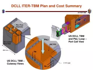
ITER test port configuration has been fixed (by ITER & TBWG) (U.S. DCLL TBM is shown for illustration of how a TBM fits into this configuration) VV – Cryostat Duct Cryostat Bio-Shield VV Port Extension TBM Frame Assy Bio-Shield Port Opening Plasma Transporter Pb-Li Primary Coolant Loop Ancillary system TBM VV Closure Plate Pb-Li Concentric Pipe Port Cell Area
Vertical Port Frame Opening space for TBM 20 Test Blanket Module Backside Shield 20 Configuration (and size) of TBM within ITER Test Port Port plug = Frame + TBMsFrame = FW structure + Box structure + Backside shields 20 mm gap all around inside frame openings Cut-view Vertical cross-section of Frame (at the center of flexible supports) 1660 TBM Frame Assembly • Port can be divided vertically or horizontally • The maximum size of a test module (half vertical port) is 1.66m x 0.484m (TBM maximum first wall area is 0.8m2) Unit: mm 484
Current U.S. TBM Plans US TBM plans evolved during the past year through technical studies, interactions with the community, VLT and DOE, as well as interactions with the international ITER partners and our work within TBWG. • TBM selected concepts and strategy. • Description of designs of TBM test articles. • External loops and ancillary equipment (piping, heat exchangers, tritium extraction, etc.)
US TBM Selected Concepts 1. The Dual-Coolant Pb-17Li Liquid Breeder Blanket concept with self-cooled Pb-Li breeding zone and flow channel inserts (FCIs) as MHD and thermal insulator -- Innovative concept that provides “pathway” to higher outlettemperature/higher thermal efficiency while using ferritic steel. --US lead role in collaboration with other parties (most parties are interested in Pb-Li as a liquid breeder, especially EU and China). -- Plan an independent TBM that will occupy half an ITER test port with corresponding ancillary equipment. 2. The Helium-Cooled Solid Breeder Blanket concept with ferritic steel structure and beryllium neutron multiplier, but without an independent TBM -- Support EU and Japan efforts using their TBM structure & ancillary equipment -- Contribute only unit cell /submodule test articles that focus on particular technical issues
Dual Coolant Lead-Lithium (DCLL) FW/Blanket Concept Idea of “Dual Coolant” concept – Push towards higher performance with present generation materials (FS) • Ferritic steel first wall and structure cooled with helium • Breeding zone is self-cooled Pb-17Li • Structure and Breeding zone separated by SiCf/SiC composite flow channel inserts (FCIs) that DCLL Typical Unit Cell Self-cooled Pb-17Li Breeding Zone SiC FCI He-cooled steelstructure • Provide thermal insulation to decouple Pb-17Li bulk flow temperature from ferritic steel wall • Provide electrical insulation to reduce MHD pressure drop in the flowing liquid metal Pb-17Li exit temperature can be significantly higher than the operating temperature of the steel structure High Efficiency
US DCLL TBM module All structures are He-cooled @ 8MPa self-cooled PbLiflows in poloidal direction SS frame Front FCI is the Thermal and MHD Insulator lining all PbLi channels FS structure PbLi in PbLi out He in Back He out PbLi in FW He counter flow PbLi out Be front face
Pb-Li Outlet Pipe FW He Coolant Manifolds Pb-Li Inlet Pipe Pb-Li Flow Separation Plate with He coolant Channels Pb-Li Inlet Manifold Pb-Li Return Flow Channel FCI Plasma Facing First Wall Pb-Li Inlet Flow Channel FW He Coolant Channels Bottom Plate He Coolant Channels
DCLL TBM Calculated Temperatures • Nominal (reference) operation (350C<He<450C;370C<PbLi<470C) FS/PbLi=462C SiC/PbLi=470C Calculations performed at k=15 W/m-K (not so important), =20 S/m • High performance (example) (350C<He<450C;450C<PbLi<620C) FS/PbLi=482C SiC/PbLi=607C Calculations performed at k=3 W/m-K (reduced to minimize heat losses into He, =20 S/m SiC/PbLi PbLi/SiC FS/PbLi He/FS
DCLL Design Temperatures For both TBM and power reactor design, the following temperature limits were designed to and can be achieved: TBM Reference operation Higher performance operation FS Tmax ≤ 550° C ≤ 550° C FS/PbLi < 500° C < 500° C SiC/PbLi < 500° C < 700° C SiC Tmax < 500° C < 700° C 350° C < He < 450° C 350° C < He < 450° C 370° C < PbLi ≤ 470° C 450° C < PbLi ≤ 650° C For the DCLL TBM higher PbLi exit temperature ~650° C can be achieved via the bypass loop without requiring high-temperature materials for external piping/HX/TX. High-temperature materials (compatible with Pb-17Li up to 700° C) will be needed for the external lead lithium loop (HX/TX tubes) ONLY for the high performance power plant (NOT for TBM, and NOT for moderate performance power plants)
DCLL TBM Bypass Loop Schematic Pump 400 C Tritium extraction tank Valve off 30.3 kg/s bypass line 180 C DCLL TBM 400 C 0 kg/s PbLi loop 8 MPa Helium loop PbLi/He Heat Exchanger Concentric pipe with FCI 470 C PbLi mixing tank 470 C 30.3 kg/s 0.4 MW 300 C Higher PbLi exit temperature can be achieved without requiring high-temperature materials for external piping/HX/TX. This can be achieved by turning the bypass valve “on” to allow mixing a lower temperature stream with the high-temperature stream in the PbLi mixing tank
Side Wall Helium-Cooled Ceramic Breeder (HCCB) Blanket/First Wall Concept for TBM Idea of “Ceramic Breeder” concepts – Tritium produced in immobile lithium ceramic and removed by diffusion into purge gas flow • First wall / structure / multiplier /breeder all cooled with helium • Beryllium multiplier and lithium ceramic breeder in separate particle beds separated by cooling plates • Temperature window of the ceramic breeder and beryllium for the release of tritium is a key issue for solid breeder blanket. Schematic view of an example ITER HCCB test blanket submodule showing typical configuration layout of ceramic breeder, beryllium multiplier and cooling structures and manifolds • Thermomechanical behavior of breeder and beryllium particle beds under temperature and stress (and irradiation) loading affects the thermal contact with cooled structure and impacts blanket performance • Nuclear performance and geometry is highly coupled and must be balanced for tritium production and temperature control
Electromagnetics/Neutronics unit cell design Unit (mm) Ceramic Breeder TBMInserting “US” unit cells into the EU HCPB structural box
Example: DCLL TBM Testing Schedule in ITER (4 sequential test articles)
DCLL TBM Pre-ITER Schedule to deliver test module one year before ITER Day One of operation
HCCB TBM Pre-ITER Schedule to deliver test submodule one year before ITER Day One of operation
TBM Materials andKey Parameters • Materials: -- DCLL: Ferritic Steel, PbLi, He, FCI (SiC or Sandwich type) -- HCCB: Ferritic Steel, Be, Ceramic Breeder (Li2TiO3 or Li4SiO4), He coolant, He purge • Maximum fluence < 0.09 MW•y/m2(< 1 dpa) • Neutron wall load: ~ 0.8 MW/m2 • Surface heat flux: maximum 0.5 MW/m2 (local) • design average 0.3 MW/m2 • maximum number of pulses: < 30,000 cycles • Ferritic Steel: maximum temperature < 550°C • FS/PbLi interface < 500°C • SiC/PbLi < 600°C (~500°C also o.k.)
Relevant MHD issues for US DCLL that impact material requirements and performance • MHD Pressure drop is a serious concern for inboard LM blankets in high field, high power density reactors. Even moderate, but non-uniform, MHD pressure drops (arising from flaws for example) can seriously affect flow balance between parallelchannels leading to hot channels • MHD velocities profiles can exhibit strong jets next to regions of stagnation and even reversed flow • Non-uniform volumetric heating can cause natural convection flows that MHD effects do not damp – can swamp forced flow velocity in slow moving breeder zone regions • Turbulence/stability modification and suppression by MHD forces and joule dissipation will likely affect performance Ha and Re numbers ~1-3 x 10⁴ All of these MHD issues strongly influence heat transfer, corrosion, tritium permeation, material requirements, and ultimate design.
=500 1/Ohm-m 100 5 20 Optimization of FCI Properties • Properties of the FCI need to be optimized in order to address competing requirements: • reduce MHD pressure drop to acceptable levels • minimize heat losses from PbLi to helium coolant • minimize temperature drop across the FCI (thermal stress) • limit RAFS/PbLi interface temperature • minimize corrosion rate ▪ minimize tritium diffusion • Optimal mix of thermophysical & mechanical properties depends strongly on the thermofluid MHD and will be determined by R&D and design tradeoffs • Properties given on another slide give some approximate goals and requirements for SiC development for the FCI Effect of on MHD jet formation Velocity normalized to vave = 0.1 m/s B = 4 T
X (poloidal) FCI Pb-17Li bulk flow He flows Fe wall Pb-17Li gap flow B-field PES Effectiveness of SiCf/SiC FCI as Electric/Thermal Insulator depends on the Thermophysical properties And Design of FCI (e.g PES VS. PEH and location relative to magnetic field) Pressure equalization opening makes the pressure on both sides of the FCI equal, resulting in almost no primary stresses. The opening is either a slot (PES) or a row of holes (PEH). Analysis shows significant MHD pressure drop reduction with FCI as compared to the case without insulation: a factor of 10 at = 500 S/m (acceptable) a factor of 200-400 at = 5 S/m (desired)
Desired Flow Channel Insert Properties • Low transverse electrical and thermal conductivity of the SiC/SiC • Goal ~1-10 S/m transverse electrical conductivity, Acceptable <500 S/m for TBM operation • Goal ~2-5 W/mK transverse thermal conductivity, Acceptable <15 W/mK for TBM operation • The inserts need to be compatible with flowing Pb-17Li • Goal ~800°C, Acceptable 500°C for initial TBM operation • Liquid metal must not “soak” into pores of the composite (or foam) in order to avoid increased electrical conductivity. In general, closed porosity and/or dense SiC layers are required on all surfaces of the inserts. • Secondary stresses and deformation caused by temperature gradients must not endanger the integrity of FCIs. • Goal 200°C temperature difference, Acceptable 100°C temperature difference for initial TBM operation • The insert shapes needed for various flow elements must be fabricable • Basic box-channel element • Cross sections up to 150 x 150 mm for TBM • Lengths 500-1000 mm for TBM
IV. What is needed from the Materials Program DCLL A) R&D for TBM B) R&D for Power Plants B1) Moderate Performance B2) Higher Performance Solid Breeders -- R&D for TBM
Material Application for FCI (and associated external piping, HX, and TX) for TBM and Power Plants (X) Requirements on σ and к for the moderate temp SiC FCI are less demanding than those for high-temperature, high performance SiC FCI * If development of high temperature SiC for power plants is available around 2015-2020, a higher performance TBM can be considered for later stages of ITER testing.
A. Needs for the DCLL TBM • Development of flow channel inserts for thermal and electrical insulation • inserts made of SiC-composite suitable for moderate temperature (< 500ºC) • inserts made of sandwich-structure (i.e. steel-alumina-steel, welded at all edges), back-up solution in case the SiC inserts can not be developed in time, suitable for lead lithium exit temperatures up to 500ºC (defer this until after the first MHD tests around 2008) • for higher performance TBM: SiC FCI for high temperature (up to 650°C) lead lithium at the exit • Fabrication of the TBM structure from RAFS (F82H or EUROFER) including forming of the complicated structure (i.e. FW panel), welding (diffusion, TiG, Laser, electron beam), PWHT. • Most of these steps are under development in the EU and Japan, and the alternative is therefore to either procure from their industry, or to develop the required technology in the US (Iteration with the detailed TBM design will be needed)
A. Needs for the DCLL TBM (cont’d) • Code-qualification of the RAFS and the welds for ITER applications • Development of suitable FE-codes for the analysis of the steel/Pb-17 Li compatibility tests and the extrapolation of these results to the conditions in a blanket ( flow conditions, impact of magnetic field, suitable criteria for determining temperature limits) • Data base for the compatibility of Pb-17 Li with RAFS and SiC-composites (e.g. forced convection loop with temperature gradients in flow direction, measurement of depositions, impact of irradiation) • Recommendations regarding suitable materials for the external lead-lithium loop including limits on the allowable interface temperatures (maximum lead lithium temperature 470ºC).
B. DCLL Material R&D for Power Plants Two kinds of operation of the DCLL blankets in power plants can be considered: B1) Moderate Performance with lead lithium exit temperatures up to 500 C and a RANKINE cycle (steam turbine) power conversion system • B1 can be realized with sandwich-type flow channel inserts and a primary loop build of well known ferritic steels B2) Higher Performance: high temperature operation with exit temperatures up to 700°C, allowing the use of a BRAYTON cycle (He turbines) power conversion system. • For B2 SiC-composite FCI are required, and the materials used in the primary loop (tritium extraction system, intermediate HX) must be compatible with Pb-17 Li up to 700°C. • Certainly, the high power operation is more attractive, but a DCLL blanket with lead-lithium exit temperatures of ~ 500°C has already a number of advantages compared to a HCLL blanket (simpler structure, no need for large internal heat transfer surfaces, less void space in tokamak inboard, smaller pumping power, tritium control easier).
B. DCLL Material R&D for Power Plants (cont’d)Common issues for both B1 and B2 cases For both kinds of power plants, the following issues have to be addressed by the material program: • Qualification of the RAFS and its welds for high fluence irradiation, • Development of suitable methods for the purification of Pb-17 Li (corrosion products, on-line Bi removal, Po control), • Tritium extraction and control (e.g. tritium permeation barriers)
B. DCLL Material R&D for Power Plants (cont’d) Issues specific to the B1 and B2 cases B1) Issues to be addressed for moderate performance power plants • Long time behavior of sandwich-type FCI , • Suitable tritium extraction system (main candidate: vacuum permeator with ferritic steel tubes), • Tritium control, especially the required reduction of permeation losses in the Pb-17Li/steam HX B2) Issues to be addressed for high performance power plants • Qualification of the SiC flow channel inserts for high temperature applications (Interface temperature SiC/Pb-17 Li up to 800 C) • Development of suitable tritium extraction methods from Pb-17 Li, leading to low tritium partial pressure (< 100 mPa), (candidate method: vacuum permeator with Nb or Ta tubes) • operational limits on the impurities in Pb-17 Li, maintain extremely low impurity level in the vacuum chamber, • impact of different materials in the primary Pb-17 Li loop : RAFS, SiC-composite, Nb-or Ta permeator tubes, HX tube material. • Development of HX between primary (Pb-17Li) and secondary (He) loops, candidate material for the HX tubes include Nb or Ta, SiC-composites, Ni-base alloy with high Al content for forming protective coatings.
Materials Needs for Ceramic Breeder TBM • Ferriticsteelstructure: needs are satisfied by those for the DCLL • Pebble ceramics and beryllium: evaluate US strategy for procurement (Do we want to collaborate with EU, Japan and other parties on development or just purchase from EU/Japanese industry?) • There is an active R&D program on ceramic breeder blankets worldwide. The US materials program may wish to explore making contributions to this area.
Additional Material Issues Common to All TBM Concepts and Parties • Development of Be/FS joining capability • Transition elements between FS in the TBM and the coolant access pipes (preferably austenitic steel for remote welding)
There are Immediate Needs for Human Resources from the Material Program to participate in the TBM activities and to work as part of the ITER TBM TEAMThose are in addition to performing the R&D described earlier For Example: • to help the team perform design trade offs, more detailed design, and analysis for the TBM test articles and associated systems • To provide advice on all aspects of materials limits and considerations • To help the team decide on key areas of and strategy for international collaboration • To assist in calculating costs for the TBM Program (including R&D, mockups, test articles, ancillary equipment, etc) (URGENT) Approximate for FY06: 1.5 – 2.5 FTE