Download
1 / 22
220 likes | 453 Views
Issues and Prospects of Silicon Carbide Composites for ITER-TBM. Yutai Katoh, Takashi Nozawa and Lance Snead Oak Ridge National Laboratory For presentation at US ITER-TBM Meeting August 10–12 , 2005, Idaho Falls. Issues of SiC/SiC Components for ITER TBM.

E N D
Issues and Prospects of Silicon Carbide Composites for ITER-TBM Yutai Katoh, Takashi Nozawa and Lance SneadOak Ridge National Laboratory For presentation at US ITER-TBM MeetingAugust 10–12, 2005, Idaho Falls
Issues of SiC/SiC Components for ITER TBM • SiC/SiC FCI for ITER DCLL Blanket System • No serious feasibility issues identified • (Dynamic chemical compatibility) • Issues related to performance and/or require design consideration • Thermal conductivity • Electrical conductivity • Deformation / internal stress • (SiC/SiC for ITER HCCB Blanket System) • Mechanical integrity issues • Helium tightness • Fabrication issues • Compatibility issues • Others • Non-destructive or proof testing
SiC/SiC FCI for DCLL Blanket Thermal Conductivity • Assumption: • Trans-thickness thermal conductivity KT < 5 W/m-K at 500°C maximum acceptable, < 2 W/m-K desirable. • In-plane thermal conductivity KIP does not matter. • Typical 2D CVI SiC/SiC with crystalline SiC fibers: • KT ~ 10 W/m-K at 500°C, unirradiated. • Neutron irradiation further decreases KT.
SiC/SiC FCI for DCLL BlanketThermal Conductivity of Irradiated CVI SiC/SiC Katoh, ISFNT-7 Hi-Nicalon Type-S CVI Composites (Snead) Unirr. Irrad.
SiC/SiC FCI for DCLL BlanketThermal Conductivity: Implications • KT of Type-S or Tyranno-SA CVI SiC-matrix composites at 500°C will be ~10 W/m-K unirradiated and ~3 W/m-K irradiated (>~1 dpa). • KT < 2 W/m-K should be achievable by (1) incorporating closed pores at around mid-plane (engineered porous mid-plane approach), or (2) impurity doping. Porous mid-plane approach is more compatible with other requirements (electrical, mechanical). • Modeling capability: • Sufficient science base exists for the estimation of irradiated thermal conductivity of SiC/SiC composites in various architectures. • Initial R&D Requirement: • Identify appropriate method(s) for engineering porous mid-plane components. Micro-porous mid-plane (Partial PIP, SiC foam) Meso-porous mid-plane (Loose stack 2D) Open core weaves (Truss core, etc.)
SiC/SiC FCI for DCLL BlanketElectrical Conductivity • Assumption: • Trans-thickness electrical conductivity sT < 500 S/m acceptable (for low pressure drop), < 20 S/m desirable, < 1 S/m admirable (flat velocity profile). • In-plane electrical conductivity sIP does not matter unless >> 103 S/m. • Typical CVI SiC/SiC: • sIP ~ 103 S/m for PyC-interphase composites (Snead, J. Nucl. Mater. 329-333, 2004, 524, Scholz et al, J. Nucl. Mater. 307-311, 2002, 1098). sIP is determined primarily by conduction through PyC (Katoh, ISFNT-7). • sT >(>>) 20 S/m for many CVI SiC matrix composites, although determined primarily by quality (impurity) of SiC matrices.
SiC/SiC FCI for DCLL BlanketElectrical Conductivity of CVD SiC and Near-stoichiometric SiC Fibers • Usual n-type CVI SiC matrix will provide high composite conductivity. • <~20 S/m at 500C may be possible for CVI SiC matrix compensated with Al, etc. (R&D required) • Irradiation (and transmutation) effect has to be confirmed for high resistivity matrix. • For <<20 S/m at >500C, alternate approaches will be necessary. R&H STD (Vender) ~60 meV (N) HNLS (Scholz, 2002) ~940 meV (?) TySA (Scholz, 2002) ~220 meV (Al) 20 S/m R&H HR (ORNL/PNNL) ~420 meV (?) 500°C R&H HR (Vender) ~470 meV (?)
SiC/SiC FCI for DCLL Blanket Measurement of Trans-thickness Electrical Conductivity • For 2-probe measurement, good Ohmic SiC-metal contacts are required. They are usually obtained using Ni, Co, etc. (contact resistivity << 10-3 ohm-cm2) • 4-probe technique is not ideal because of the flat specimen geometry and structural non-uniformity. However, there will be a way to analytically derive trans-thickness conductivity. A V A V
SiC/SiC FCI for DCLL Blanket Methods for (Semi-) Insulating SiC-based Matrices R&H STD Fibers 20 S/m 1 S/m R&H HR V-doped, Sublimation (Mitchel et al) Insulating interlayer High Purity (Ellison et al) SiCN Layer V-doped, Implantation (Kimoto et al) SiC Matrix 500°C 1000°C Fiber Graded insulating interlayer Impurity doping / purification
SiC/SiC FCI for DCLL Blanket Electrical Conductivity: Implications • Trans-thickness electrical conductivity (sT) of standard CVI SiC-matrix composites at 500°C will be in order of 100 – 1000 S/m. Combined with porous mid-plane approach, maximum acceptable <500 S/m will be achieved. • Compensated or purified ‘high resistivity’ matrix combined with porous mid-plane may achieve sT ~ 20 S/m. R&D required. Transmutation effect needs attention. • For sT < 20 S/m, more effective measure will have to be taken. Options include (1) incorporation of insulating interlayers [eg. oxide], (2) incorporation of (semi-) insulating matrix second phase [eg. SiCN], and (3) doping for semi-insulating SiC matrix [V]. • Initial R&D Requirements: • Establish a reliable technique to measure trans-thickness electrical conductivity at elevated temperatures. • Identify appropriate method(s) for engineering porous mid-plane components. • Survey applicability of high resistivity matrix to CVI composites. • Identify a few most promising methods for (semi-)insulating SiC-based matrices, and develop R&D plans for them. • Develop strategy to identify irradiation and transmutation effect. (High resistivity SiC in 18J)
SiC/SiC FCI for DCLL Blanket Deformation and Internal Stress Issues • Trans-thickness temperature gradient (DT ) in FCI walls causes: • Deformation in the non-constrained direction • Internal stress in the constrained direction • Responsible mechanisms: • Differential thermal expansion (Deth) • Differential irradiation-induced swelling (Des) • Insufficient pressure equalization gives external stress • Need assessment • Analytical capability: • Deformation and/or internal stress can be analyzed based on currently available material data and assumed / modeled properties for wall structure specific to FCI, ignoring the effect of irradiation creep. • Irradiation creep may play a key role in moderating the internal stress.
SiC/SiC FCI for DCLL Blanket Differential Thermal Expansion t = 5 mm L = 200 mm a = 4.5E-6 K-1 DT = 200 K Deth= 0.09% R ~ 5.6E+3 mm q ~ 2.1° D ~ 0.9 mm E = 200 GPa smax ~ 90MPa • Deformation due to differential thermal expansion: • Mid-point deflection (D): • Thermal stress when flexurally constrained: • Thermal stress may cause interlaminar shear failure for poorly-infiltrated 2D composites or matrix cracking in dense composites. t DT L R q
60°C Swelling of beta-SiC (single-beam) 200°C 400°C 600°C 800°C 1000°C 1200°C 1400°C ? SiC/SiC FCI for DCLL Blanket Lattice Swelling of SiC Pramono, et al. ~8x10⁻⁶ K-1 ~6.8x10⁻⁶ K-1
SiC/SiC FCI for DCLL Blanket Differential Swelling t = 5 mm L = 200 mm b ~ 8E-6 K-1 DT=200 K Des= 0.16% R ~ 3.1E+3 mm q ~ 3.7° D ~ 1.6 mm E = 200 GPa smax ~ 160 MPa • Bend radius (R) due to differential swelling: • Mid-point deflection (D): • Thermal stress when flexurally constrained: • This will cause interlaminar shear failure in poorly-infiltrated 2D composites and may induce matrix micro-cracking in properly infiltrated 2D composites. t DT L R q
SiC/SiC FCI for DCLL Blanket Effect of Irradiation Creep on Time-evolution of Internal Stress due to Differential Swelling: Preliminary Model Analysis E = 200 GPa • Substantial irradiation-induced internal stress will develop at <1 dpa due to differential swelling. • No credible data are available for irradiation creep compliance of SiC.
SiC/SiC FCI for DCLL Blanket Deformation and Internal Stress Issues : Implications • Differential thermal expansion (Deth) and differential swelling (Des) due to the trans-thickness temperature gradient (DT) result in bending and/or internal stress in FCI. • Bending and/or internal stress due to Deth and Des occur in opposite signs but would not cancel each other; Deth occurs immediately after starting operation, whereas Des develops over a long period. • Both Deth and Des result in slight distortion onto cross-sectional geometry (non-constrained) and may impose substantial internal stress in longitudinal bending (constrained). • The internal stress may be reduced by (1) architectural design for low flexural modulus, (2) geometrical design that allows longitudinal bending deformation, and (3) irradiation creep. • Action / Initial R&D Requirements: • Thoroughly assess external stresses. • Confirm if expected cross-sectional distortion is within design allowance. • Develop material design strategy for low flexural modulus and compatibility with other requirements (eg. porous mid-plane) • Develop FCI design strategy that allows longitudinal bending deformation of each face. • Develop method to determine stiffness matrix of relevant materials. • Develop research plan to be able to predict irradiation creep compliance of FCI material.
SiC/SiC FCI for DCLL Blanket Summary / Perspective • 2D composites, poorly or more properly infiltrated, will achieve the minimum insulation requirements. Mechanical integrity under thermal stress will be the primary issue for such 2D composite FCI. Flexure and interlaminar shear are the most likely failure modes. • Electrical conductivity can be substantially reduced by incorporation of oxide or SiCN matrix interlayers. These two approaches areindustriallyavailable and therefore feasible with limited R&D effort. • Thermal insulation and the thermal stress are incompatible issues, unless employing suitable architectural fabric features. The architectural approach will be feasible,as several appropriate specialty weaves are commercially available.
SiC/SiC FCI for DCLL Blanket SiC/SiC FCI Envisioned for Two R&D Cases Minimum R&D Extensive R&D Poorly-Infiltrated 2D Standard SiC Matrix Thin PyC Interphase KT(irr) = ~3 W/m-K sT = ~100 S/m Design has to account for very weak interlaminar shear strength Architecturally Designed 3D Insulating SiC-based Matrix PyC Interphase KT(irr) = ~1 W/m-K sT << 1 S/m Enhanced tolerance against internal shear stress
SiC/SiC FCI for DCLL Blanket R&D Items (preliminary proposal) • For electrical (and thermal) insulation: • Establish a reliable technique to measure trans-thickness electrical conductivity of SiC/SiC plates at elevated temperatures. • Identify appropriate method(s) for engineering porous mid-plane components, compensated high resistivity SiC matrix, and insulating SiC-based matrices. Trial-fabricate flat plates of these composites and evaluate baseline properties. • Perform small scale irradiation experiment (rabbit type) on insulating SiC matrix composites. • For mechanical integrity: • Perform detailed evaluation of cross-sectional and longitudinal stress / strain due to thermal gradient. Interact with design community. • Design materials / components for low flexural / trans-thickness shear moduli and compatibility with other requirements (eg. porous midplane) • Determine stiffness matrix and other design properties for FCI material. Develop appropriate test methods. • Determine irradiation creep compliance of FCI material. • Perform mock-up (-like) testing to ensure mechanical integrity and sealing are maintained up to design maximum thermal gradient.
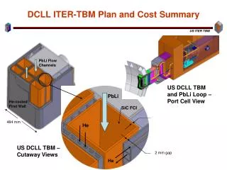
Estimated SiC/SiC FCI Cost • Assumes a square tube of 1m x 20cm x 10cm x 5mm(t). • Matrix infiltration: 50-100k • Fiber (20% Vf): ~30k (Hi-Nicalon™ Type S) / ~10k (Tyranno™-SA3) • Weaving: ~50k • Total cost per tube: 100-200k
SiC/SiC FCI for DCLL Blanket R&D Plan (preliminary proposal)