Download
1 / 67
670 likes | 692 Views
Klaus F öhl, PANDA Cerenkov workshop in Glasgow, 11 May 2006. Disc DIRC. ... the intended agenda. quick orientation for non-pandas brief particle ID motivation Cherenkov radiation flypast lightguides and simulations photo readout and B-field Plexiglass? Temperature! ToP

E N D
Klaus Föhl, PANDA Cerenkov workshop in Glasgow, 11 May 2006 Disc DIRC
... the intended agenda ... • quick orientation for non-pandas • brief particle ID motivation • Cherenkov radiation flypast • lightguides and simulations • photo readout and B-field • Plexiglass? • Temperature! • ToP • Test Experiments ...
the current GSI Gesellschaft für Schwerionenforschung
the new FAIR SIS100/300 planning as of 2004 Facility for Antiproton and Ion Research
Antiprotons at FAIR SIS100/300 Panda HESR planning as of 2004 1 GeV/c – 15 GeV/c
PANDA Side View AntiProton ANihilations at DArmstadt Pbar ANDA
Particle ID in PANDA 22 degrees 5 degrees
Particle ID & Kinematics - + + K K K K even or K - + + - pp KK T=5,10,15 GeV/c pp DD D Kpp T=6.6 GeV/c + + - + + - - + + + pp i.e. charmonium production + D distinguish and K (K and p) ... if mass known, particle identified For what channels do we not have this factor 2-3 reduction? need to measure two quantities: dE/dx energy momentum velocity momentum (tracking in magnetic field) velocity (Cherenkov Radiation) momentum (tracking in magnetic field) velocity (Cherenkov Radiation)
Cerenkov Radiation Cerenkov angle depends on particle speed the cone gives a ring image on a detector plane <1 =1 material with a different dispersion prism: correcting dispersion chromatic dispersion lens: turning angle into position parallel light paths
DIRC: BaBar-type versus Disc 4-fold direction ambiguity angle and edges crucial 2-fold ambiguity in disc, lifted at readout only parallel surfaces required
Solid Angle onto flat surface conserving angles and circles 45 90 degrees
Light transmitted in DISC conserving angles and circles 45 90 degrees
Colour fringes on rings conserving angles and circles 45 90 degrees
coordinates measured at rim 45 90 degrees
3-prong event in DISC 45 90 degrees
DIRC Detector Idea polynomial coefficients: c2= -3.0/(60^2) c3= -0.5/(60^3) c4= -0.1/(60^4) side view side view LiF front view LiF fused silica 5cm completely within medium all total reflection compact design all solid material flat focal plane focussing is better than 1mm over the entire line chosen as focal plane fused silica
Lightguide-Designs polynomial coefficients: c2= -3.0/(60^2) c3= -0.5/(60^3) c4= -0.1/(60^4) polynomial coefficients: c2= -5.4/(60^2) c3= -0.9/(60^3) c4= -0.5/(60^4) focussing is better than 1mm over the entire line chosen as focal plane • possibly difficult design requirements: • vertical focal plane (normal to B-field) • short focal plane (high dispersion deg/mm)
Status of simple Disc Simulations • perfect surfaces • proper directions • recent improvements • true 3D • analysis of pixel hits • in the pipeline • angular straggling -important for (e,) and (,) • further optimising • include upstream tracking (necessary?) • NOT: • no diffraction • no polarisation • no background (particles and photons) • no maximum likelihood analysis • not free of minor approximations (KISS)
status of simulations vertex provided position provided all from DISC data 64 lightguides (no pixels) 128 (no pixels) REALLY PRELIMINARY unpixelised focal plane no chromatic correction nondispersive materials fluctuations numerical artefact - it’s on the “to do” list...
further optimisation • resolution scaling with pixels • resolution not scaling with pixel size 4 (momentum resolution) ~ (pixel number * quantum efficiency)
Yoke Solenoid Housing Solenoid and Yoke Environment
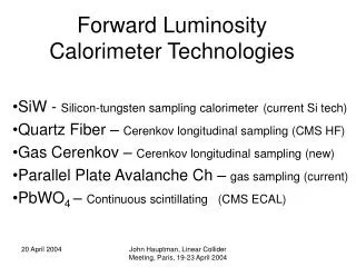
Photon Detectors • phototubes • APDs • channel plate phototubes • optical fibres and external phototubes • HPDs with magnetic imaging
Position-sensitive Phototubes B-field probably too strong H8500 H9500 R3292 10cm
Yoke Light guide or fibre readout? determination determination
HPD with magnetic imaging Klaus Föhl 2-June-2004
Silicon Strip Detector photocathode B E E fused silica B photocathode Silicon Strip Detector fused silica - - e e HPD readout possible? possibly higher quantum efficiency in reflective photocathode geometry
Temperature • cold solenoid, cold EMC • maybe coolde APDs • SiO2, LiF different expansion coefficients • dew, condensation on surfaces
Yoke Radiation Countermeasures? what radiation fields? do we need radiation shielding? will PB act:- -as absorber -or as converter?
Plexiglass as Cerenkov radiator? • transmission • SiO2 300-600nm N0/mm=14 • plexi400-600nm N0/mm= 7 • radiation hardness • BaBar “Spectrosil” proven • plexiglass “hamm wer doa” not proven • but: radiation length X0 three times larger • 36cm versus 12cm (40.5g/cm2 vs 26g/cm2) more photons per X0 less chromatic dispersion no UV-grade material necessary (glass, glue, PMT) • focussing optics probably ok for thicker radiator • availability? time stability? radiation hardness? higher lower dispersion maybe not such a stupid idea maybe not such a stupid idea
Time-of-Propagationin a dispersive medium • Light propagation speed perpendicular • to Cherenkov-light-emitting particle track: • =300nm photon is 6% slower than 600nm • larger Cherenkov angle – 2% shorter path • 4% time difference (=600nm is “faster”) • difference equivalent to =0.04 for 120cm radial distance ToP=8.3ns (400nm) 0.33ns spread in arrival time fused silica (aka quartz) 6% 2%
ToP in DISC – some thoughs... • chromatic time correction – do not see how (I see no space for red light to run extra length) (unless photon detector timing can be made colour-dependent) • disc not self-timing “GPS altitude problem” • external time reference should be 100ps/sqrt(N) • if time reference from target vertex factor 2 better overall situation equivalent to 4.5 metres TOF • >>50*multiplicity pixels needed • multiple hits can be separated if spaced apart
Towards Test Experiments • Radiator slab (fused silica, plexiglass) • Focussing lightguide • Edinburgh workshop: • perspex: ok • quartz: we are happy to try (difficulties anticipated) • photon readout • DAQ
Material Test Testing transmission and total internal reflection of a fused silica sample (G. Schepers and C. Schwarz, GSI)
Outline • FAIR international accelerator facility • Particle ID – the physics requirements • Cerenkov Radiation • DIRC in PANDA • Detector performance • Conclusions and Outlook working on Cerenkov detectors for PANDA: Edinburgh, GSI, Erlangen, Gießen, Dubna, Jülich, Vienna, Cracow, Glasgow
Pion-Kaon-Separation fused silica plate 10mm thickness (density 2.2g/cm thus 8% radiation length) detection efficiency 20% (=300-600nm) centre hole 3 K 64 segments in each with 48 rectangular pixels overall 3072 pixels K K threshold -1 figure of merit N = 152cm N(ideal) = N x 1cm x sin () = 82 geometric transmittance N(detected) = 82 x 0.61 = 50 0 2 0
Conclusions • optical properties of this design are good enough • performance depends on number of pixels • optical test bench • phototubes + electronics • operational detector slice • testbeam experiments
Side View 2000mm 1500mm 10mm fused silica plate (density 2.2g/cm , 8% radiation length) plate radius 1500mm , detection plane radius 2000mm wavelength range 300-600nm, detection efficiency 20% figure of merit N = 152cm N(ideal) = N x 1cm x sin () = 82 N(detected) = 82 x 0.61 = 50 geometry transmittance 3 -1 0 2 0
Photon Lines in space particle vertices target point
Lensing cylinder lense N.B. to be compared with 10mm pixel height spread over prism width
Chromatic Correction higher dispersion glass spread =300nm to 600nm
Lensing cylinder lense N.B. to be compared with 10mm pixel height spread over prism width
Chromatic Correction higher dispersion glass spread =300nm to 600nm
Chromatic Correction higher dispersion glass + effective pixel height spread =300nm to 600nm
Poynting vector wavefront Cherenkov radiation c