Download
1 / 32
320 likes | 337 Views
The TWiLiTE project aims to develop an advanced airborne scanning direct detection Doppler lidar to measure full profiles of winds. This update provides an overview of the project requirements, error budget, instrument development status, and key technologies.

E N D
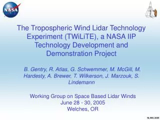
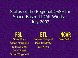
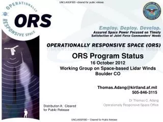
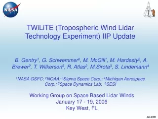
TWiLiTE (Tropospheric Wind Lidar Technology Experiment) IIP UpdateB. Gentry1, G. Schwemmer6,M. McGill1, M. Hardesty2, A. Brewer2, T. Wilkerson5, R. Atlas2, M.Sirota3, S. Lindemann41NASA GSFC; 2NOAA; 3Sigma Space Corp.; 4Michigan Aerospace Corp.; 5Space Dynamics Lab; 6SESI Working Group on Space Based Lidar Winds January 17 - 19, 2006 Key West, FL
TWiLiTE Overview Requirements and Error Budget WB57 Aircraft Instrument Development Status Summary Outline
TWiLiTE Project Organization Project Management PI – Gentry PM, Sys Eng – Sirota, Chauvet, Mathur Science Requirements and Applications Atlas,Gentry, Hardesty, McGill, Brewer… Aircraft accomodations WB57- McGill, Chauvet GIV – Brewer, Hardesty HOE Telescope/ Scanner POC:Schwemmer Supplier: SDL Laser POC: Li Supplier: TBD Doppler Receiver GSFC POC: Gentry Mech: Cooperider, Optics: Bos I&T : Scott Thermal: Greer C&DH Sigma POC: Machan System Integration/ ‘Glue’ Sigma POC: Mathur 355 nm HOE’s Wasach Photonics Ralison FP Etalon MAC Lindemann 10 Ch MCS+ Sigma Machan
Proposed TWiLiTE Measurement Requirements * Assumes scanner average angular velocity of 12 deg/sec
16 point step stare scan pattern Top view • Scanning parameters: • Constant dwell of 10s/LOS • Scanner angular velocity of 12 deg/sec • 192 sec to complete one cycle Radial HLOS wind speed measured in a single range bin for 3 cycles of the 16 point step stare scan pattern. Assumes constant velocity (maximum = 40 m/s)
Top level error budget (4 W laser) Total LOS velocity accuracy 2.0 m/s Photon shot noise 1.75 m/s Doppler receiver spectral calib 0.35 m/s Laser spectral 0.25 m/s AC motion comp. 0.25 m/s Margin 0.8 m/s Total error =2.0 m/s = 1.752 + 0.352 + 0.252 + 0.252 + 0.82
WB57 Instrument Mounting 3’ pallet 6’ pallet Looking forward from inside the payload bay Pallet integration
Engine On Take Off Steep Ascent Slow Ascent Cruising
Three axis accelerometer data from WB57 at operating altitude - Flight 2, 12/18/2005
Volume reduced by 90% versus current GLOW receiver Optical path lengths minimized to improve mechanical, thermal stability End-to-end throughput increased by 60% Signal dynamic range increased by 2 orders of magnitude IRAD Receiver Design Summary
Discretely ‘stepped’ plate creates three spectrally distinct resonant cavities Plate steps of 20.2 nm and 70.7 nm Plate reflectivity of 73% @ 355 nm Surface flatness of l/150 @ 633 nm Intragap capacitive feedback provides direct knowledge of gap dynamics Capacitors fabricated from Expansion Class 0 Zerodur for minimal thermal contributions Stacked ring piezoelectric actuators provide > 3 microns dynamic range Closed loop operation provides sub-nanometer resolution of motion Invar construction provides thermal stability and mechanical robustness Vibration tests to confirm operation in aircraft environment scheduled in early February Michigan Aerospace TWiLiTE Etalon Design Features
Michigan Aerospace TWiLiTE Etalon Invar housing machined from solid piece ensures material homogeneity, rigidity and minimizes thermal deformation ‘Soft’ diaphragm mounting on actuated ring allows for tuning with a minimal amount of stress imparted to the ring/plate assembly while holding the etalon rigidly centered on optical axis. 3 point rigid mount at input creates stress free reference plane and stable angle of incidence
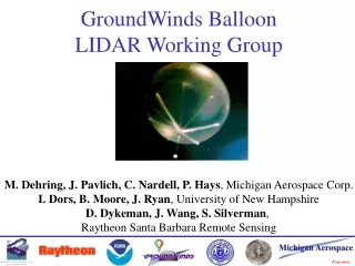
TWiLiTE Holographic Telescope FUNCTIONS • Collect and focus laser backscatter • Scan laser and FOV • Provide pointing knowledge to CDH FEATURES • Primary Optic: Rotating 40-cm HOE, 1-m f.l. • 45-deg off-nadir FOV • Compact, folded optical path • Coaxial laser transmission • Active laser bore-sight
TWiLiTE Telescope Team Geary Schwemmer (SESI) – lead POC Space Dynamics Lab Team Thomas Wilkerson – SDL lead Brent Bos (GSFC) –Optical Engineering Jason Swasey – Lead Engineer Caner Cooperrider(GSFC) Mechanical Eng. Jed Hancock – Optical Engineering Brian Thompson – MechanicalEngineering Adam Shelley – Mechanical Engineering Marc Hammond – consultant Richard Rallison (Wasatch Photonics) – HOE consultant
TWiLiTE System Concept- As of Dec. 2005 TWiLiTE System Integrated on 3 foot pallet Enclosure proposed to mitigate environmental extremes
TWiLiTE Milestones *Project Start August, 2005
TWiLiTE Summary • The TWiLiTE IIP is a three year R&D project to design and build an airborne scanning direct detection Doppler lidar • The primary objective is to advance the TRL of key component technologies as a stepping stone to space. • At the end of the project we will have a fully autonomous, integrated Doppler lidar designed to measure full profiles of winds from a high altitude aircraft. • We are actively seeking input on the instrument design requirements from the community. This includes input on potential applications, target field experiments, etc for the TWiLiTE instrument.
Backscattered Spectrum DOP Aerosol (l-2) Molecular (l-4) Frequency Doppler Lidar Measurement Concept • DOPPLER RECEIVER - Multiple flavors dependent on scattering target - • Aerosol return gives high accuracy and high spatial and temporal resolution when aerosols present • Molecular return gives lower accuracy and resolution but signal is always there
High altitude airborne direct detection scanning Doppler lidar • Serves as a system level demonstration and as a technology testbed • Leverages technology investment from multiple SBIRs, ESTO, IPO and internal funding • Consistent with the roadmap and planning activities for direct detection and ‘hybrid’ Doppler lidar implementations
Photon shot noise v err 1.75 m/s Optical throughput (Mean value and vs polarization,T,P and grms) Laser HOE collecting area Boresight and alignment • Laser • Far field diverg • Pointing jitter • FOV • fiber diam • HOE fl • HOE • Spot size • Rotational/optical axis alignment • Bearing TIR • HOE/laser mechanical mounting • Active alignment mechanism • Energy • (mean, jitter and drift) • PRF • Seeding efficiency • Spectral purity • Transmit optics • HOE receiver • Diffraction eff • Transmission • Doppler receiver • End to end trans per edge channel • PMT QE • Etalon transmission • Fiber optic • coupling • attenuation • bulkhead feedthru Spatial and temporal Averaging
Doppler receiver v err 0.35 m/s Etalon spectral (Mean value and vs polarization,T,P and grms) PMT Optical constants Atmospheric effects (vs altitude) • Temperature • Density (Rayleigh Brillouin lineshape) • Backscatter ratio • Clouds • QE • Response linearity • Dynamic range • Instrument function (total response measured in calibration) • Etalon finesse • Plate flatness • Angluar broadening (pinhole finesse) • Gap (FSR) • Plate parallelism • Edge channel separation • Intensity split ratio of edge channels
Laser spectral 0.25 m/s Laser linewidth at 355 nm Laser reference measurement • Laser frequency stabilty (jitter and drift) over measurement interval • Etalon locking channel finesse and transmission • analog PMT response • analog sampling and detection (‘boxcar’) • number of shots averaged per ref meas
A/C motion compensation 0.25 m/s • Knowledge of Aircraft ground speed and direction • Transceiver pointing angle measured in instrument reference frame Coarse Doppler compensation offset (receiver or laser) if used • Aircraft orientation (Pitch, roll, yaw) measured in instrument reference frame by POS
TWiLiTE Schedule • August 2005 start • Initial Test Flights in 2008