CESR-c Status
This document presents an in-depth analysis of the CESR-c performance metrics, focusing on design parameters and compensation techniques employed to enhance beam dynamics. We discuss the implementation of superconducting wigglers, solenoid compensation schemes, and the impact of beam parameters on emittance and stability. Detailed measurements of radiation damping times, injection rates, and luminosity projections are provided alongside simulations comparing weak-strong beam interactions. Future remediation plans and ongoing studies are explored, aiming to optimize the performance towards achieving the desired energy reach of 1.5-6 GeV per beam.

CESR-c Status
E N D
Presentation Transcript
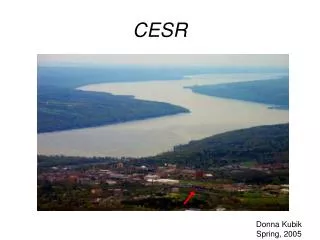
CESR-c Status CESR Layout - Pretzel, Wigglers, solenoid compensation Performance to date Design parameters Our understanding of shortfall Plans for remediation Instrumentation Ongoing studies Projections
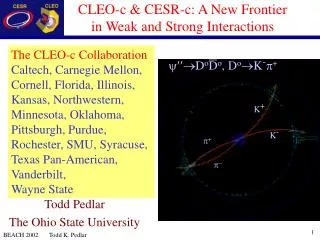
CESR-c Energy reach 1.5-6GeV/beam Electrostatically separated electron-positron orbits accomodate counterrotating trains Electrons and positrons collide with ±~3.5 mrad horizontal crossing angle 9 5-bunch trains in each beam (768m circumference)
12 superconducting wigglers 1.4 T < Bpeak < 2.1 T - Reduce radiation damping time from 500ms to 50ms at 1.9GeV beam energy Injection rate damping rate Instability thresholds damping rate Increased beambeam limit, tolerance to long range beam-beam effects - Increase emittance from 30nm to ~100-200nm
CESR-c Energy dependence • Damping and emittance control with wigglers
7-pole, 1.3m 40cm period, 161A, B=2.1T Superconducting wiggler prototype installed fall 2002
Solenoid compensation scheme • PM, Q1, Q2 are rotated 4.5 degrees about axis, designed to compensate 1.5T solenoid at 5.3 GeV • Skew quad coils are superimposed on Q1 and Q2 for fine tuneing and energy reach • Skew quad 3, is third component in “3-pair” compensation scheme • The first bending magnet is immediately beyond skew quad 3 PM Q2 Q1 sk_q03e Skew quad 3 sk_q03w CLEO solenoid
Wiggler Beam Measurements • Injection 1 sc wiggler (and 2 pm CHESS wigglers) -> 8mA/min 1/ = 4.5 s-1 6 sc wiggler -> 50mA/min 1/ = 10.9s-1
Wiggler Beam Measurements6 wiggler lattice • Injection 30 Hz 68mA/80sec 60 Hz 67ma/50sec
Wiggler Beam Measurements • Single beam stability 6 sc wigglers 2pm + 1 sc wigglers 1/ = 10.9s-1 1/ = 4.5 s-1
Performance D303.2004, 8X5, *=12mm
Performance D303.2004
Performance Integrated/day Including best day Integrated from start Of cesrc
CESR-c Energy dependence • In a wiggler dominated ring • 1/ ~ Bw2Lw • ~ Bw Lw • E/E ~ (Bw)1/2 nearly independent of length • (Bw limited by tolerable energy spread) Then 18m of 2.1T wiggler • -> ~ 50ms • -> 100nm-rad < <300nm-rad
Performance vs design Bunch current 2mA/bunch vs 4mA/bunch Limited by parasitic interactions (Single bunch current limit > 4mA) Our scaling from 5.3GeV beam energy neglected contribution to beam size from energy spread and high field wigglers => large energy spread Beam current 8X5 vs 9X5 (ion effects) Beam beam tune shift parameter Large energy spread, energy dependence of solenoid compensation dilutes beam size at low current Large energy spread, small * => high synchrotron tune, synchrobetatron resonances limit tune shift at high current
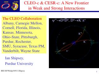
Weak strong beambeam simulation • Comparison with measurements • In simulation, tune scan yields operating point • Data: Assume all bunches have equal current and contribute equal luminosity CESR-c 1.89 GeV, 12 2.1T wigglers Phase III IR
Weak strong beambeam simulation • Comparison with measurements • In simulation, tune scan yields operating point • Data: Assume all bunches have equal current and contribute equal luminosity 5.3GeV Phase II IR CESR-c 1.89 GeV, 12 2.1T wigglers Phase III IR
Weak strong beambeam simulation • Lifetime Loss of 1 of 5000 particles in 100 k turns => 20 minute lifetime CESR-c 9X5 CESR-c 9X4 Measure lifetime limited current ~ 2.2mA/bunch(9X5), ~2.6mA/bunch(9X4)
Compensating solenoid PM Q2 Q1 Skew quad CLEO solenoid
+ Qz=0.05 + pQx+qQy+rQz=n |p|+|q|+|r| ≤3 Qz=0.1
+ Qz=0.05 + pQx+qQy+rQz=n |p|+|q|+|r| ≤4 Qz=0.01
Longitudinal emittance • 12 wigglers, 1.89GeV/beam • E/E ~ 0.084%, ~ 50 ms, h = 120nm • p = 0.0113 • v* = 12mm • Then l = 12mm => Qs= 0.089 • Element M inserted in ring opposite IP • Then l = 12mm => Qs= 0.049 or Qs =0.089 => l = 7.3mm
Longitudinal emittance • Reduced momentum compaction and no solenoid
Instrumentation Turn by turn position at IP Fast luminosity monitor Bunch by bunch luminosity Bunch by bunch position/beam size Streak camera
(magnification ~ 3.6) Palmer
Ongoing study Nonlinearities Optical distortion due to parasitic crossings Resonance remediation Low momentum compaction optics