Download
1 / 15
150 likes | 302 Views
James A. Crittenden Laboratory for Elementary-Particle Physics Cornell University 27 June 2006. Operational Status of CESR-c. CESR Storage Ring and Injectors. CESR-c Operation since 2003 12 s.c. wigglers since mid-2004 1.5-6 GeV beam energy Presently 2.085 GeV 768 m circumference

E N D
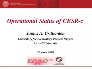
James A. Crittenden Laboratory for Elementary-Particle Physics Cornell University 27 June 2006 Operational Status of CESR-c
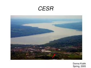
CESR Storage Ring and Injectors CESR-c Operation since 2003 12 s.c. wigglers since mid-2004 1.5-6 GeV beam energy Presently 2.085 GeV 768 m circumference 24 bunches/beam 60 mA/beam The electron and positron beams are separated by means of electrostatic separators. The optical distortions introduced by this “pretzel” orbit are corrected using the lattice design flexibility afforded by 180 quadrupole and sextupole magnets.
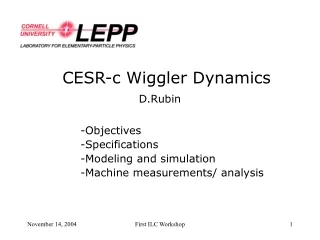
CESR as a Charm Factory CLEO-c and CESR-c: A New Frontier in Weak and Strong Interactions CLNS 01/1742 October 2001 Physics Motivation Unprecedented statistical precision for decays of charm-quark bound states Increase world data sample by two orders of magnitude CESR provides unique opportunities 1) Decades of design and operating experience with the CESR storage ring and injectors 2) CLEO state-of-the-art detector technology 3) Threshold production kinematics Success contingent on meeting major accelerator physics challenges Design and operation of first wiggler-dominated storage ring
From 5.3 GeV 4s)) to 1.9 GeV s)) Severe consequences for lowering beam energy • Emittance • Energy spread • Damping time and injection rate • Beam-beam kicks and tune shifts • Single-bunch instability thresholds • Intra-bunch scattering Twelve 2.1-Tesla 130-cm-long superconducting wiggler magnets to restore damping • Emittance: 30 g 220 nm-rad • Damping time: 570g55 ms • Energy spread: 2 x 10⁻⁴g 8 x 10⁻⁴ a Need flexible design capability Vertical tune shift 0.1 per wiggler !
8-pole Superconducting Wiggler Magnets 8 poles (4 x 20 cm, 2 x 15 cm, 2 x 10 cm) Central poles: 660 turns, 95 kA End poles: 352 turns, 51 kA (trim adjust) In-house design & construction 2001-2004 Installation complete August, 2004 Beam-based characterization of wiggler nonlinearities accurately modeled for three-wiggler cluster in-situ. Analytic wiggler field model uses Taylor mapping for fast tracking simulation. Tune Shift (kHz) Vertical beam displacement: ±10 mm Field Modeling for the CESR-c Wiggler Magnets, J.A. Crittenden et al., PAC2005
Commissioning Milestones 8/2002 First wiggler installed 9/2002 Machine studies verify wiggler properties 10-12/2002 Engineering run 90 mA, 1x1031 7/2003 New vertex chamber in CLEO 8/2003 Five more wiggler magnets 11/2003-4/2004 First Physics run 110 mA, 3x1031, (3x world sample of y(3s)) 4-6/2004 Complete installation of 12 wigglers 8-9/2004 Install fast luminosity monitor 9/2004-3/2005 Production run at 3770 MeV, 160 mA, 6x1031, (y(3s) X 4) 8-9/2005 Ds scan 12/2005-1/2006 Ds Production (4170 MeV) 1-2/2006 Install new solenoid compensation magnets 3-4/2006 Ds Production (3X), 120 mA, 7x1031, injection into collision
Luminosity History CESR-c: Performance of a Wiggler-Dominated Storage Ring A. Temnykh, PAC2005 • Developments since PAC 2005 • New IR Optics • Electron Injection into collision • BBI included in lattice design • Constraint on e+e- symmetry • New diagnostic tools Diagnostics of Interaction Point Properties and Bunch-by-Bunch Tune Measurements in CESR, G.W.Codner et al, Beam Instrumentation Workshop 2006
CESR-c Operating Parameters Design report 20014/20054/2006 ℒ(1030 cm-2 s-1) 300 65 70 Ibeam (mA) 180 75 65 Nr Bunches 45 40 24 H (nm-rad) 220 135 120 xV 0.04 0.024 0.029 b V (cm) 1.0 1.2 1.2 sE/E (10-4) 0.81 0.85 0.81 tH,V (ms) 55 50 55
Improved Solenoid Compensation New IR Compensation Scheme 2006 Skew-quadrupole compensation of CLEO detector solenoid was implemented in 2001 and used for 5.3 GeV operation. Full CESR luminosity modeling in early 2005 indicated that the energy-dependence of compensation is more important at CESR-c energy due to larger energy spread Two-solenoid solution was DAfNE-inspired, but optics design was complicated by existing permanent and s.c. quadrupoles Two 36-inch-long 2-Tesla “anti-solenoids” installed in January, 2006
Improved Tune Plane Footprint New solenoid compensation reduces strength of synchro-betatron resonance improved ease of machine tuning Solenoid strength reduced 20% Residual coupling compensated using IR skew quads Nominal Solenoid Compensation Vertical Tune (kHz) Horizontal Tune (kHz)
Topping Off: Reliability & Duty Cycle Ability to inject and collide in similar optics avoids fill-to-fill thermal cycling Tune excursions from BBI much reduced (less hysterisis!) Turn-around times reduced from 4 to less than 2 minutes. March 26, 2005 April 8, 2006
Modelling the CESR-c BBI These recent improvements in IP optics, tune plane footprint and duty cycle re-emphasize the importance of finding a way to compensate optical distortions arising from the beam-beam interaction. Beam-beam kicks
Present Operational Limit Studies of the Beam-Beam Interaction at CESR, M.G.Billing and J.A.Crittenden, MUOPLS043, EPAC06 Calculating and Compensating the Optical Distortions Arising from the Beam-Beam Interaction Present stored-current limit: 2.5 mA in 8x3 operation in collision, but higher if the beams are separated at the IP . Limit on a single electron bunch into 8x3 positrons is 8 mA. As a result, much effort has been put into modeling the beam-beam interaction both at the IP and at the parasitic crossings. Some improvement has been obtained already by including consideration of the long-range BBI in the lattice design. Nonetheless, the distortion of the beta function is substantial, even when the tunes are held constant during filling. Present current limit Until now, operational compensation of the BBI effects has consisted of global tune corrections. We have recently developed an optics correction algorithm based on locally closed beta bumps using eight quadrupole magnets around each set of crossings. Initial results from machine studies in April, including compensation of the BBI at the main IP, are encouraging.
Near-term Improvement Plans Machine Studies Projects July-September 2006 • Lattice design development, e.g. pretzel optimization • Tune IP BBI compensation (empirical coefficients) • Tune local parasitic crossing compensation • Improve e- injection efficiency • Sextupole tuning to avoid resonances • Study alternative working points • Develop run-time tuning aids • Improve hardware reliability through diagnostic tools • Injector tuning • Tune, tune, tune ...
Completion of CLEO-c Physics Program During the past year, modeling of CESR-c operation has resulted in • new IR optics; new solenoids have been built and installed • improved understanding of the effects of the beam-beam interaction • lattice design optimization including BBI effects • development of BBI compensation algorithms Bunch-by-bunch and turn-by-turn diagnostic tools have been commissioned. Stability and reliability have been enhanced by the ability to inject electrons into collision. CLEO/CESR continues to be major contributor to the active field of charm spectroscopy. Discovery of new bound states of charmed quarks, precision measurements of form factors, and many first-time observations coincide with increasing precision of lattice QCD phenomenology. CLEO presently dominates the world sample of y(3770) and Ds threshold data and is on track to increase former by factor two and latter by factor four. The foreseen program also includes tripling world sample of y(3686) decays by the time of its completion in April, 2008. The primary operational tool for compensating the beam-beam interaction at CESR has been global tune adjustment employing all quads to compensate the beam-beam interactions. At points of horizontal (vertical) separation, these have a defocusing effect in the horizontal (vertical) plane and a focusing effect in the vertical (horizontal) plane, while focusing in both planes at the main interaction point. The tune shift at the interaction point is typically five time greater than that from all the parasitic crossings, so the primary operational adjustment is to reduce tune globally as the colliding current increases. Such a global adjustment necessarily results in local distortions of the phase function. We are presently developing a compensation method based on local phase distortion correction using the 8 quadrupoles surrounding each of the sets of three parasitic crossings. Six quantities are compensated: horizontal and vertical phase advance, and the sine and cosine components of the beta function. We have demonstrated during machine studies experiments that the correction coefficients for the near-IP crossings are effective in compensating the distortions arising from the IP itself. Modelling results of both the beta function distortion and the dynamic aperture indicate that the operational current limit may be raised by 50%.