3D Building Reconstruction from LiDAR Data.
291 likes | 749 Views
Our approach A data driven approach that determines building parameters from the LiDAR point cloud. No initial model is assumed, except that the roof consists of planar regions only. A data-mining approach is employed to extract information.

3D Building Reconstruction from LiDAR Data.
E N D
Presentation Transcript
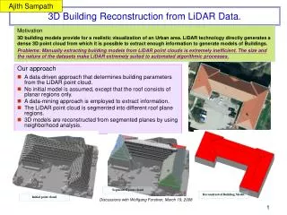
Our approach A data driven approach that determines building parameters from the LiDAR point cloud. No initial model is assumed, except that the roof consists of planar regions only. A data-mining approach is employed to extract information. The LiDAR point cloud is segmented into different roof plane regions. 3D models are reconstructed from segmented planes by using neighborhood analysis. Ajith Sampath 3D Building Reconstruction from LiDAR Data. Motivation 3D building models provide for a realistic visualization of an Urban area. LiDAR technology directly generates a dense 3D point cloud from which it is possible to extract enough information to generate models of Buildings. Problems: Manually extracting building models from LiDAR point clouds is extremely inefficient. The size and the nature of the datasets make LiDAR extremely suited to automated algorithmic processes. Segmented point cloud Reconstructed Building Model Initial point cloud Discussions with Wolfgang Forstner, March 19, 2008
Building Roof Segmentation To segment LiDAR points into roof segments. generate building models from Laser scanned point clouds over urban areas. Assumptions: Planarity of the roofs. The building roofs are piecewise planar. Main ideas of the approach Curvature and Surface Normals characterize any surface. Under the constraint of planarity, surface normals are sufficient. Surface normals are defined only for differentiable and continuous surfaces. Use Eigenvector and Eigenvalue analysis to softly-identify regions of non-differentiability. Assign a measure between 0 and 1 to each LiDAR return 0 indicates a discontinuous surface with no confidence in the normal vector estimates in that region 1 indicates complete confidence in the normal vector estimates. Use subtractive clustering on normal vector estimates from continuous regions to determine estimates of all the plane segments Refine Clustering using surface normal of all points in a Gaussian Mixture like approach. 3D Building Reconstruction from LiDAR Data. Some Key Issues in Clustering • Each feature vector (normal vector) gets an a-priori confidence measure. • Initial Clusters and their locations approximated using density values around a neighborhood “r”. • Further refinement of cluster centers is based on the feature vector’s distance from cluster center. • Clusters generated for several values of “r” and the similarity measure plotted to determine actual clusters. • The “Elbow Joint” is taken as the actual number of clusters present in the data. Planar Points Initial point cloud Further Segmentation • Each Cluster may represent several planes in same direction (i.e. same Normal vector) • In the equation Ax+By+Cz+D=0, D is calculated for each point {Xp,Yp,Zp} represented in a cluster. • Points are segmented based on values of “D”. • Planes may be further segmented based on connectivity. Discussions with Wolfgang Forstner, March 19, 2008 The “Elbow Joint” curve Direction Segmented Points
Building Roof Reconstruction To Reconstruct the Building model from the segmented Planes. Building Reconstruction • The distance between two planar segments (P & Q) in a roof is defined as: • A neighborhood Matrix is then generated. The matrix shows all mutually intersecting planes. • Any two intersecting planes are selected, and all planes that intersect both of them are enumerated, and solved. • For instance Planes {1,4,10} and {1,4,13} are solved to get the breakline (A-B)as shown. 3D Building Reconstruction from LiDAR Data Issues and Future Work • Segment and Reconstruct non planar parametric roofs. • Extract and map texture from Images Discussions with Wolfgang Forstner, March 19, 2008
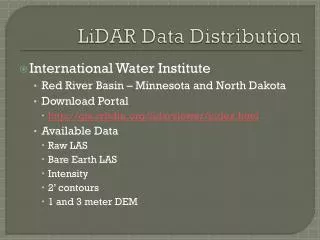
Local Convex Hull Approach to Boundary Extraction in LIDAR Point Clouds Jun Wang • Convex Hull • A set in a vector space is called a convex set if the line segment joining any pair of points of lies entirely in • The convex hull of a set of points S in d dimensions is the minimal convex set containing S • Convex hull can quickly capture the rough shape or pattern of the points set Construct a Convex Hull Find the lowest point (anchor point) Form a nonitersecting polygon by sorting the points in order around the anchor point Remove the non-convex vertex from the polygon • Common Algorithms • Graham's Scan, Gift wrapping, Divide and Conquer, QuickHull, etc. • QuickHull package: supports 2-d, 3-d, and higher dimensions http://www.qhull.org/ Objective • Develop automatic boundary discovery algorithms that works on LIDAR point clouds directly • Avoid high computation-cost global Interpolation or triangulation • Based local topology, no prior assumption on point clouds Discussions with Wolfgang Forstner, March 19, 2008
Local Convex Hull Approach to Boundary Extraction in LIDAR Point Clouds • Design Ideas • Binary classification of the points: boundary point/non-boundary point • Sculpture the unknown surface boundaries by removing the “non-boundary” points defined by local convex hull • Nearest Neighbors based computation, low computation memory requirements Non-Boundary Point Boundary Point • Boundary Labeling Algorithm • Input: {points, n} • For all the points • Pick up n nearest neighbors of point p • Construct the convex hull • Labeling all the points insides the convex hull as “non-boundary” points. • Output: {non-boundary points |boundary points} Local Convex Hull and Non-Boundary Points • Theorem: for a convex set S, pick up any subset of points contain point p, if p is inside the convex hull of the subset of points, then p is not on the boundary of the convex hull of points S • Detect non-boundary points with local convex hull formed by their nearest neighborhoods Discussions with Wolfgang Forstner, March 19, 2008
Local Convex Hull Approach for Boundary Extraction in LIDAR Point Clouds 66.44 Height 0.64 Testing on LIDAR data • R tree supported fast nearest neighborhood search in point clouds • The advanced version to detect boundaries on vertical walls and inside surface patches, such as roof structures is under development. Discussions with Wolfgang Forstner, March 19, 2008
Application of active contour based on level set to identify buildingboundary from LIDAR data KyoHyouk Kim Application of LIDAR data for delineation of building outline and roof topology Automation in data acquisition and 3D reconstruction for 3D urban models has been an important research area, and many researchers have proposed and applied various kind of methods using high-resolution satellite images or aerial photographs. In these days, LIDAR data is widely used to reconstruct 3D building models. To delineate the building boundary and roof topology, we aimed to apply “active contour” based on level-set methods into dense point clouds data. • Our approach • Application of traditional active contour based on level-set method into dense point clouds data and check the possibilities for further research. • Application of multi-phase level set method to delineate the inner topology of building roof. • Propose a new stopping function criterion adequate for roof topology delineation. Rottensteiner Discussions with Wolfgang Forstner, March 19, 2008
Application of active contour based on level set to identify buildingboundary from LIDAR data Methodology: By Chunming Li et al, 2005 Total energy function : , where is an external energy and is an internal Energy. And, external energy function can be described as follows. , g is a “edge-stopping” function Therefore, geometrically, the external function represents the length And the inner area of zero level curve of The final evolution equation of curve is Initial DSM 600 iteration 300 iteration 756 iteration Discussions with Wolfgang Forstner, March 19, 2008
Application of active contour based on level set to identify buildingboundary from LIDAR data • Problem and possible solution (1) • Evolution of curve didn’t stop at outer boundary of building having gradient roof • This problem might be solved if we apply a different stopping function not based on edge. • Problem and possible solution (2) • Traditional level set method can’t delineate the inner boundary of the gradient roof. • We may apply multi-phase motion level set method from inner seed pixel or initial boundary of each planar roof segment. • Problem and possible solution (3) • Computational complexity • We may apply “Narrow band” algorithm to achieve computational efficiency Gradient roof building Multi-phase motion level-set Simultaneous evolution of curve Discussions with Wolfgang Forstner, March 19, 2008
Building extraction and delineation is one of the most salient problems in cartographic features extraction. This study presents a semi-automatic framework for reliable and accurate building extraction from high-resolution color imagery focusing on building boundary delineation and building roof compositional polygon segmentation. The framework for building extraction consists of three steps. Anisotropic diffusion and clustering (pre-processing) for de-noising and color quantization Buildingboundary extraction using active contours driven by edge-flow. Building roof compositional polygons segmentation by JSEG. Yonghak Song BUILDING EXTRACTION FROM HIGH RESOLUTION COLOR IMAGERY BASED ON EDGE FLOW DRIVEN ACRIVE CONTOUR AND JSEG Problems • Many automatic building extraction methods from DEM or multi-spectral imagery suffer from rough delineation result due to the relatively low resolution of the involved DEM and multi-spectral imagery. • Low resolution and deficiency of the method cause the fact that several buildings and possibly their surroundings are extracted as one building. • Therefore, the results can only used as an initial approximation to the final building and must be enhanced with improved reliability and further refined for better accuracy. Strategy for Building Extraction Discussions with Wolfgang Forstner, March 19, 2008
J-image generation (Deng et al. (1999) ): measuring local homogeneity Apply the k-means clustering J= the distances between clusters / the distances within each cluster Edge-flow generation (Total edge energy and likelihood ) Boundary tracking by active contours Edge flow vector field: external force, measure J: stopping function Re-clustering with k-mean and regenerate J-image watershed segmentation refinement by merging and removing segments according to some criteria. BUILDING EXTRACTION FROM HIGH RESOLUTION COLOR IMAGERYBASED ON EDGE FLOW DRIVEN ACRIVE CONTOUR AND JSEG METHODOLOGY 1. Color Space Conversion and Anisotropic Diffusion • Color space conversion : RGB space > CIE L* a*b* space • CIE L* a*b* space : L* - luminance, a*b* - color. • Separation of achromatic information from chromatic information • Uniform color space- allow Euclidean distance • Similarity to human visual system. • Anisotropic diffusion • Selective smoothing : decrease noise and enhance color information • Use Heat conduction equation (initial: Image, C-coefficient:: gradient) 2. Building Boundary Delineation using Active Contour 3. Building Roof Polygon Extraction Discussions with Wolfgang Forstner, March 19, 2008
In spite of noisy boundary, proposed framework shows correct localization of the building boundaries. Also it yields reliable wireframes of building roof. However, determined roof compositional polygon is incorrect in some cases (bottom left result ). Shows over-delineation of building roof due to over-segmentation (red circle) Lost several wireframes because of under-segmentation. (blue circles) BUILDING EXTRACTION FROM HIGH RESOLUTION COLOR IMAGERYBASED ON EDGE FLOW DRIVEN ACRIVE CONTOUR AND JSEG RESULT AND CONCLUSION RESULT CONCLUSION & FUTURE WORKS • This study present a framework to segment buildings from high resolution color imagery based on the JSEG method and edge flow driven active contours. • It shows good result in some case but this result is not consistent. Because the performance of proposed method totally relies on intensity and color information in image, adjacent roof facades which have same reflectance values due to the same incident angles with sunlight can not be separated. This also leads the need of additional information such as DEM that can be incorporated with the proposed algorithm. Discussions with Wolfgang Forstner, March 19, 2008
Yonghak Song AUTOMATED ROCK SEGMENTATION FOR MARS EXPLORATION ROVER IMAGERY Mars Exploration Rover Mission The Mars Exploration Rover mission is an ongoing robotic mission to explore the Martian surface by rovers, “spirit” and “opportunity” Objectives • Make maps showing the locations of different kinds of rocks and soils around the landing sites. • Search for and study many different types of rocks and soils that might hold clues to past water activity. Prerequisite of mission is to detect and to classify rocks and soils. MER Pancam-Main camera for rock detection • Pancam's imagery is designed to help scientists decide what rocks and soils to analyze in detail, and how to interpret the results. • Also provides information on the surface features of the area around the rover, the distribution and shape of nearby rocks, and the presence of dunes and features carved by ancient waterways.” Pancam image Rational of study • Autonomous interactive capability to perform the scientific mission • Image compression by prioritizing rocks for effective data transmission • 1024x2048 pixel CCD array detectors 1024 x 1024 image • Effective focal length: 43mm • FOV : 16 degree by 16 degree • IFOV: 0.28 mrad/pixel Maintain focus 1.5m~infinity • 8 filters per camera Problem for rock image segmentation • Rock has different intensities due to various reflections • Segmentation only with intensity leads Over segmentation • Merging procedure is needed • Rock has more homogeneous in terms of texture than intensity Image segmentation based on the texture has advantages • Texture-based segmentation can’t offer sharp rock boundary Add boundary refinement step using active contours Two-stage solution for rock segmentation • Rock detection using texture based image segmentation • Rock boundary refinement by edge-flow driven active contour based on level set method Discussions with Wolfgang Forstner, March 19, 2008
AUTOMATED ROCK SEGMENTATION FOR MARS EXPLORATION ROVER IMAGERY Rock Detection using Texture Analysis • 1. The multi-channel approach • Transform an image to a new set of features that offer condensed, classification related information • Exploit Haar wavelet transform to use its four coefficient channels: the approximation, horizontal, vertical and diagonal detail coefficients • Texture based image segmentation • Multi-channel approach (A) • Multi-resolution histogram (B) • Inter-scale decision fusion (C) • 2. Multi-resolution histogram • From each channel, the texture features are extracted by measuring the change of histogram with respect to the image resolution relying on the wavelet decomposition level • Such histogram change reflects the variation of spatial information, i.e., texture measured by the generalized Fisher information content. • 3. Inter-scale decision fusion • Integrate the texture features at different scales through their statistical relationships for better texture classification • Use two adopted k-means algorithms: hierarchical and interactive k-means Multi-resolution histogram Effect of inter-scale fusion Detected rocks using texture Discussions with Wolfgang Forstner, March 19, 2008
AUTOMATED ROCK SEGMENTATION FOR MARS EXPLORATION ROVER IMAGERY Boundary refinement using active contours Edge flow (flow direction + edge energy) • The flow direction determined by the first directional derivatives of the Gaussian kernel • The edge energy represented as a flow vector by assigning probabilities to its flow direction. • The edge flow forms the vector field as an external force to enforce the initial boundaries towards the pixels with high probability of rock boundary edges The texture-based image segmentation yields reliable rock segmentation results but they are too rough to determine accurate rock boundaries. Hence, the rock boundaries are refined, by edge-flow driven active contour based on the level set method, which adopt “edge flow” concept to compensate the problems of traditional active contours that are sensitive to noise and often cause the edge-leaking problem Refined rock boundaries Edge flow-driven active contour by level set method • Compute the edge flow vector • Generate the stopping function from the edge flow vector field by solving • Propagate initial boundary using following equation Example of topographic correction Stopping function Edge flow vector field Discussions with Wolfgang Forstner, March 19, 2008
Our approach The operators ONLY collect topological distinct points from the building roof without rules. Each building will have an unstructured point cloud set. A building could be a single or multiple point datasets based on the complexity of building structure. Each point set will be constructed as a building unit. Computational algorithms start from forming the unit boundary, then generating the unit roof. The entire building is the combination of building units. Complete buildings will be geometric models with topological information, no surface texture. Sherry Fu A semi-automatic approach to large scale 3D building reconstruction Current 3D building modeling issues The demanding of a great amount urban 3D building objects is eager for various applications. The most practical, economic and accurate approaches to reconstruct large scale 3D building models with detail structures are semi-automatic approaches with image-based data. In the semi-automatic approach: operators detect building information; automated tools reconstruct building models. The conventional photogrammetric methods require operators to delineate the building footprints and roof structures. Problems: manual building detection process is time consuming and labor intense. • To improve the efficiency, the detection processes have to be simplified. • To increase the successful rate, algorithms for reconstruction process need no constraint on building types. Discussions with Wolfgang Forstner, March 19, 2008
Boundary reconstruction The problem: to construct a compact reasonable representation of the surface from a given unstructured point set. Assumptions: building boundary properties. Either the interior angle or the exterior angle of each intersection tends to be as close to a right angle as possible. If the interior angle or exterior angle is not a right angle, both of them like to avoid acute angles. Main idea of the approach Constructing an initial convex polygon. Examining every angle of the polygon. Modify the polygon which edges cause the conflict with the assumptions. Point selection: pick breakthrough points for edges modification. Edge selection: pick up the edge needs modification most The selections are based on scoring their geometric properties: Height, Length, and Angle. Repeating the process until the polygon can no longer be modified. A semi-automatic approach to large scale 3D building reconstruction Initial point cloud Problems • No unique solution guarantee. • The accuracy is influenced by the degree of building complexity. • Sensitive to the point measurement quality. Building boundary Discussions with Wolfgang Forstner, March 19, 2008
A semi-automatic approach to large scale 3D building reconstruction Roof reconstruction The problem: no rule to follow because of the complexity of roof styles. Assumptions: roof nature based on observation. • Roof ridges tend to align with boundary edges. • Roof ridges tend to parallel to the ground. Building boundary with pre-defined roof ridges. Main idea Naturally form the shape of roofs using triangulation methods. Work on the triangulation in two-dimension phase. Approach • Find roof ridges parallel to the boundary and level to the ground. • Make a tin by Delaunay triangulation. • Applied Constrained Delaunay triangulation for disagreement edges. Create a Delaunay triangulation for the entire points. Remove the edges disagree with each other. Remaining problems • Need to develop building formulas based on symmetry, and Euler formula for regular roofs to compensate inaccurate results instead of operator post editing. • Combination of building units faces adjustment and topological problems. • Buildings can not be reconstructed by approaches, need an additional process from operators’ auxiliary. Applied Constrained Delaunay Triangulation to reconstruct conflict part. Remove redundant edges and merge adjacent triangles if coplanar. The final result is roof polyhedron. Discussions with Wolfgang Forstner, March 19, 2008