Download

1 / 19
190 likes | 400 Views
ppt on UML(Unified Modeling Language) is provided by urgenthomework.com.

E N D
UML(Unified Modeling Language) Presented by http://www.urgenthomework.com/uml-homework-help.php
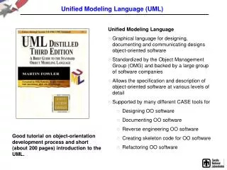
What is UML? UML stands for Unified Modeling Language. It is modeling language used for designing graphics design. It is standard language for specifying, visualizing, constructing and documenting the artifacts of software system. UML diagrams are important part of developing object oriented software and the software development process.
Use of UML • UML is an open standard, Graphical notation for specifying, visualizing, constructing and documenting software systems. • Support for UML in many software package like Rational, plugins for IDE like NetBeans, Eclipse. • By the diagram view the understanding/communication of product to customer and developers Increases. • Support for diverse application areas
Use case diagram • overview the usage requirements • presentations project stakeholders • "the meat" of the actual requirements Actor: An actor is a person, organization, or external system that plays a role in one or more interactions with your system Use case: A use case describes a sequence of actions that provide value to an actor and is drawn as a horizontal ellipse
Example of Use Case detail System boundary Actor Use case Online shopping
Class Diagram Class diagrams show the classes of the system, their interrelationships (including inheritance, aggregation, and association), and the operations and attributes of the classes.
Example of Class Diagram Name • Associations • Aggregation • Generalization Relations Attributes Operations
Activity Diagram • UML 2 Activity diagrams helps to describe the flow of control of the target system, such as the exploring complex business rules and operations, describing the use case also the business process. It is object-oriented equivalent of flow charts and data-flow diagrams (DFDs).
Example of Activity Diagram Activity Diagram Branch Start Action End
Object Diagram • Object Diagrams is similar to class diagrams. It is UML structural diagram that shows the instance of the classifiers in models. It uses notation that is similar to that used in class diagrams. It shows the static design of system but from the real prospective.
Example of Object Diagram Object
Component Diagram • Component Diagram represents how components are wired together to form longer component or software system. The purpose of the component diagram is to show h relationship between different components.
Example of Component Diagram Component Connection
Sequence Diagram • Sequence Diagram is also called interaction Diagram which shows the way that how he process operates with one another. It focus on the message interchange between a numbers of lifeline. It models the collaboration of the object based on a time sequence. The following nodes are used in UML Sequence Diagram: • Lifeline • Execution Specification • Message • Combined Fragment • Interaction Use • State invariant etc…
Example of Sequence Diagram Sequence-Actor Action Message
Deployment Diagram • In UML the Deployment Diagram models the physical deployment of artifacts on nodes. It also helps to model the physical aspect of an Object-Oriented software system. In this type of UML Diagrams nodes are appear as boxes and the artifacts allocated to each node appear as rectangles within the boxes. • For an example: If we want to describe a web site with Deployment Diagram then the hardware components i.e. “nodes” exists ,what software components i.e. “artifacts” run on each node and how different pieces are connected. • There are two types of Nodes: • Device Node • Execution Environment Node
Example of Deployment Diagram Connection Nodes