Engine Overall
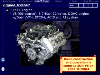
-A. Engine Overall. 3UR-FE Engine V8 (90-degree), 5.7-liter, 32-valve, DOHC engine w/Dual VVT-i, ETCS-i, ACIS and AI system. Basic construction and operation is same as 3UR-FE on 2007 TUNDRA. -A. Engine Overall. Features. MRE Type VVT Sensor. Delivery Pipe with Pulsation Damper Function.

Engine Overall
E N D
Presentation Transcript
-A Engine Overall • 3UR-FE Engine • V8 (90-degree), 5.7-liter, 32-valve, DOHC engine w/Dual VVT-i, ETCS-i, ACIS and AI system Basic construction and operation is same as 3UR-FE on 2007 TUNDRA
-A Engine Overall • Features MRE Type VVT Sensor Delivery Pipe with Pulsation Damper Function Separator Case for PCV Hydraulic Lash Adjuster Vacuum Actuator Type ACIS Dual VVT-i 4 Timing Chains 4 Flat Type Knock Sensors Engine Coolant Distribution Pathway Water Jacket Spacer Long-reach Type Spark Plug Element Replacement Type Oil Filter Spiny Liner
-A Engine Overall • Specifications
-A Engine Overall • Major Difference from 3UR-FE on 2007 TUNDRA
-A Reference (Engine Overall) • Comparison with 1UR-FSE on LS460 • Specifications
-A Reference (Engine Overall) • Comparison with 1UR-FSE on LS460 • Major Difference
-A Valve Mechanism Same as 2007 TUNDRA • Timing Chain • To ensure highly accurate valve timing, separate primary timing chains are used Primary Chain (RH) Secondary Chain (LH) Chain Tensioner (for Secondary) Secondary Chain (RH) Chain Tensioners (for Primary) Chain Tensioner (for Secondary) Primary Chain (LH)
-A Valve Mechanism Same as 2007 TUNDRA • Dual VVT-i • Hydraulic type VVT-i is used for intake and exhaust valve Hydraulic VVT-i for Intake Hydraulic VVT-i for Exhaust
-A : Oil Flow : Coolant Flow Lubrication System Same as 2007 TUNDRA • Oil Cooler • Laminated aluminum core oil cooler is used for compact, lightweight and high radiation performance Oil Filter Bracket Spacer Laminated Type Oil Cooler Oil Filter Cap
-A Cooling System Same as 2007 TUNDRA • Engine Coolant Distribution Pathway • Cylinder head and cylinder block is cooled by coolant from the engine coolant distribution pathway Engine Coolant Distribution Pathway
-A Intake and Exhaust System Same as 2007 TUNDRA • Exhaust Manifold • Air injection pipe is provided for the air injection system Air Injection Pipe Exhaust Manifold (RH)
-A Intake and Exhaust System • Main Muffler • 2-way exhaust control system is used to decrease the back pressure Control Valve Low Engine Speed (Valve Closed) High Engine Speed (Valve Opened) Reduce noise Decrease back pressure
-A Fuel System Same as 2007 TUNDRA • Delivery Pipe • Pulsation damper function is integrated in the delivery pipe Pulsation damper function Delivery Pipe Inner Pipe Fuel
-A Fuel System Same as 2007 TUNDRA • Injector • The injector wire harnesses are combined into a single connector at each bank for improved serviceability Injector Wire Harness (RH Bank) Injector Wire Harness (LH Bank)
-A Blowby Gas Oil Mist Oil Oil Separator Mechanism : Fresh Air : Blowby Gas PCV Same as 2007 TUNDRA • Separator Case • Oil separator mechanism is included to the separator case and cylinder head cover becomes compact PCV Valve Separator Case
-A Engine Control System Same as 2007 TUNDRA • Knock Sensor • 4 knock sensors are installed at inside of V-bank knock Sensor Front
-A Engine Control System Same as 2007 TUNDRA • Air Injection System • The air injection system to quicken the warming-up the TWC during the cold start-up Air Injection Control Valves Air Filters Electric Air Pumps TWC
-A Air Injection Control Driver Air Pressure Sensor Electric Air Pump Engine Control System Same as 2007 TUNDRA • Air Injection System • System Diagram • Engine Coolant Temperature Sensor • Mass Air Flow Meter • Intake Air Temperature Sensor ECM Air Injection Control Driver Air Pressure Sensor Air Switching Valve Air Switching Valve Electric Air Pump For Bank 1 For Bank 2
-A Engine Control System Same as 2007 TUNDRA • Air Injection System • Location • Air Injection Control Valve (Bank 1) • Air Switching Valve • Air Pressure Sensor • Air Injection Control Valve (Bank 2) • Air Switching Valve • Air Pressure Sensor Inlet Front Electric Air Pump (Bank 1) Electric Air Pump (Bank 2)
-A Engine Control System Same as 2007 TUNDRA • Air Injection System • Location Air Injection Control Driver (Bank 1) Air Injection Control Driver (Bank 2)
-A Engine Control System Same as 2007 TUNDRA • Air Injection System • Electric air pump supplies air into the air injection control valve Air Filter (Maintenance Free) Impeller Electric Air Pump (Bank 1) DC Motor Electric Air Pump (Bank 2)
-A Engine Control System Same as 2007 TUNDRA • Air Injection System • Air injection control valve consists of an air switching valve that switches the air to exhaust port ON/OFF Air Injection Control Valve For Bank 1 Air Pressure Sensor For Bank 2 Air Switching Valve Reed Valve
-A Engine Control System Same as 2007 TUNDRA • Air Injection System • Air injection control driver actuates electric air pump and air switching valve ECM Electric Air Pump Actuation Request AIRP SIP Air Injection Control Driver (Bank 1) Air Switching Valve Actuation Request AIRV SIV AIDI DI Failure Status (Duty) SIP2 ARP2 Air Injection Control Driver (Bank2) Electric Air Pump (Bank 1) ARV2 SIV2 Air Switching Valve (Bank 1) AID2 DI2
-A Engine Control System Same as 2007 TUNDRA • Air Injection System • Air injection control driver transmits failure status to ECM via duty cycle signal from DI terminal 80% 20% +B GND +B 0% GND +B 100% GND +B 0% GND 20% +B GND 40% +B GND 60% +B GND A: Electric air pump and air injection control valve are actuating B: Conditions other than A
-A Reference (Engine Control System) Same as 2007 TUNDRA • Air Injection System • DTCs for air injection system (1/2)
-A Reference (Engine Control System) Same as 2007 TUNDRA • Air Injection System • DTCs for air injection system (2/2)
-A Engine Control System Same as 2007 TUNDRA • Fuel Pump Control • Fuel pump ECU controls the fuel pump speed in 3 steps Fr Fuel Pump ECU
-A Engine Speed Injection Volume M Engine Control System Same as 2007 TUNDRA • Fuel Pump Control +B Hi: Mid: Lo: OFF: 0V 12 msec ECM Fuel Pump ECU Fuel Pump Operation Signal FP+ FPC FPC Fuel Pump Diagnosis Signal DI DI FP- Normal: 10V Abnormal: 0V
-A Engine Control System Same as 2007 TUNDRA • ECM • Dash panel penetration installation Body ECM ECM Gasket (Non-reusable Part)