Download
1 / 18
180 likes | 415 Views
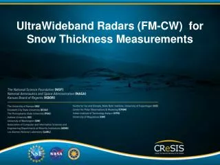
UltraWideband Radars (FM-CW) for Snow Thickness Measurements. Outline. Introduction Typical FM-CW Radar Background FM-CW radars design considerations Results Sea ice Land Future Conclusions . Basic FMCW Concept and some issues. f. Transmit Receive Mixed (Beat Freq ). k.

E N D
UltraWideband Radars (FM-CW) for Snow Thickness Measurements
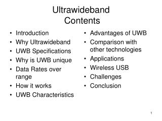
Outline • Introduction • Typical FM-CW Radar • Background • FM-CW radars design considerations • Results • Sea ice • Land • Future • Conclusions
Basic FMCW Conceptand some issues f Transmit Receive Mixed (Beat Freq) k FFT t fB=kτ • Mixing the tx and rx signals produces single tone cw signals. • FFT transforms into target delay. • Transmitting and receiving at the same time. • Transform has sidelobes (windowing and amplitude variations). • Linear Chirp Considerations: for slow chirps and close targets, chirp non-linearities are near coincidental in tx and rx and tend to cancel.
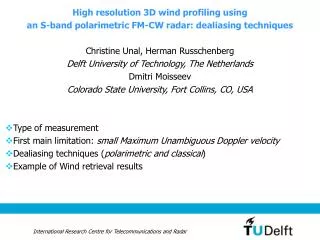
Basic FM-CW Conceptand difficulties with airborne applcations f f Fast chirp to sample Doppler (High PRF) and avoid target de-correlation. Longer range t t • Airborne applications require fast chirps and far targets. • Even slight non-linearities can cause major degradations. • Loss in resolution and FFT sidelobes.
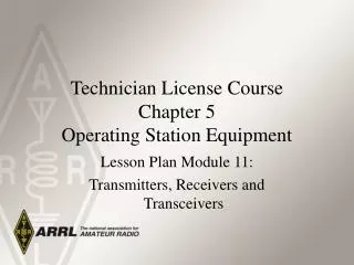
FM-CW Radar • Application of FM-CW radars for snow studies started in 1970s • Used linearized VCOs • YIG oscillators • Surface-based systems • Interfaces mapping was demonstrated • A number of systems have been built and used • Ultra-Wideband >500 MHz • FM-CW • Easy to implement • Low-sampling • Low power • Disadvantages • Linearity • RX/TX Isolation • Sidelobes
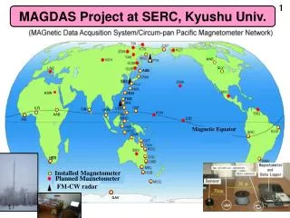
Background 2-18 GHz Surface-based • We started our work in 2000 • Small grant from NASA to develop a system • Collaboration with Thurston Markus, GSFC • Instruments being used on aircraft • Long-range • Short-range Fast chirp problems Airborne, 2006
Background • Solved chirp problems in 2008 • Fast-settling PLL + ultrawideband VCO
Typical FM-CW Radar Antenna Feedthrough Two antennas Fast Chirp Fast PLL +VCO DDS + Multiplier LO feedthrough High isolation amp Multiple reflections Minimize cables and connectors
DC-8 and P-3B Antenna Configurations MCoRDS, Accumulation, Snow, and Ku-band radars
Results – Greenland 2011 Snow Radar Ku-band Radar 0.9 km 0.9 km 10 m 10 m
Future • Backscatter data at number frequencies • Invert data to estimate snow density and particle size • Combine these with sounder-mode data to determine snow thickness • Extend frequency range • 2-18 GHz • 1-17 GHz • Quad polarization • Digital beamforming • 16-32 receivers • Measure backscatter as function of incidence angle
Array Performance Ideal 8-element array patterns at 5, 10 and 15 GHz 2D infinite dual-pol array simulation
Conclusions • Advances in RF and Digital technologies enabled us: • To develop low-power and high sensitivity ultrawideband radars • Wide use over sea ice • FCC permit to operate over land