Download
1 / 10
100 likes | 253 Views
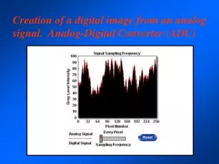
The AQuA Converter An Analog Memory Cell. Micah O’Halloran Prof. Rahul Sarpeshkar Analog VLSI & Biological Systems Group Jan. 25, 2002. Uses of analog memory:. Circuit Offset Compensation Self-Tuning/Adaptive Circuits Learning Algorithms (Speech Processing, Robotics)

E N D
The AQuA ConverterAn Analog Memory Cell Micah O’Halloran Prof. Rahul Sarpeshkar Analog VLSI & Biological Systems Group Jan. 25, 2002
Uses of analog memory: • Circuit Offset Compensation • Self-Tuning/Adaptive Circuits • Learning Algorithms (Speech Processing, Robotics) • General Memory Element
Two exisiting approaches to analog storage: • Floating-gate transistors • A/D/A converters
Floating-Gate Transistors A true analog voltage is stored on an SiO2 isolated floating gate using hot-electron injection and tunneling.
Analog-to-Quantized-Analog (AQuA) Converter • No explicit digital conversion takes place • Uses clock as a quantizing tool
AQuA Operation Overview Step 4 – Csample charges until Vo2 is high on a positive clock edge. Iclk is set so that Vo2 rises between the 2N-1 and the 2N clock edge (N is the number of bits we are quantizing to). Step 5 – The conversion is complete once we reach a positive clock edge and Vo2 is high. Step 3 – Csample asynchronously resets to zero when the voltage Vc1 reaches Vref1 . It then holds until the next positive clock edge. Step 2 – Begin charging both caps Step 1 – Sample Vin
Conclusion • The circuit was designed as a proof-of-concept of the AQuA idea, and achieved six bits of resolution. • The resolution of the implemented AQuA algorithm is very sensitive to the tuning of its parameters. • The design of a micropower 10-bit AQuA using a new more robust algorithm is currently underway.