Download
1 / 23
230 likes | 330 Views
Introduction Why copper Fabrication steps Shaping of half-cells and extremities Dimensional control half-cells Welding tests Dimensional control dumb-bells Extremities RF measurements Shape accuracy by CMM vs. RF Trimming half-cells Welding dumb-bells RF measurements of dumb-bells

E N D
Overview • Introduction • Why copper • Fabrication steps • Shaping of half-cells and extremities • Dimensional control half-cells • Welding tests • Dimensional control dumb-bells • Extremities • RF measurements • Shape accuracy by CMM vs. RF • Trimming half-cells • Welding dumb-bells • RF measurements of dumb-bells • Trimming dumb-bells • Planning • Conclusion
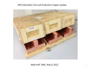
Introduction Copper cavity Two copper cavities(mock-up) are under fabrication: • To learn from the fabrication of the copper cavity for the niobium cavity. • To carry out RF measurements on the dumb-bells and complete cavity with the HOM. • For surface treatment purposes
Why copper? Copper cavity • Similar mechanical properties • Good electrical conductor • Less expensive • OFE Copper: 17 €/kg • Niobium: 470 €/kg
Fabrication steps RF measurement Nb Spinning Mtlg control Machinning RF measurement Degreasing +Cp Degreasing +Cp Spinning Metrology control HALF- CELL Machining – Weldingpreparation (Iris & rings) Degreasing +Cp EBW Dumb-bellassembly Degreasing+Cp Stiffening rings assembly RF measurement Cuttingdumb-belllength RF measurement Degreasing+ Cp EBW EBW RF measurement DUMB-BELL RF measurement Degreasing +Cp Trimmingcellslength
Fabrication steps Spinning Extrusion Machinning Degreasing + Cp Extrusion Degreasing +Cp Spinning Machining Nickeling Nickeling SS Flange-Nickling Assemblyflange + bushing Machining Degreasing +Cp BRAZING Degreasing +Cp SMALL FLANGES Brazing Machining Cu SS SS Flange-Nickling Assemblyflange + bushing Machining Degreasing +Cp Nickeling Nickeling Degreasing +Cp BIG FLANGE Brazing Machining Cu SS EBW EBW 2x
Fabrication steps RF measurement EBW Assemblyextremities & half- cell RF measurement Machinning RF measurement Degreasing +Cp Cuttingcellslength Tack-weld- EBW EBW Assemblyextremities & dumbbells Tack-weld- EBW EBW Tack-weld- EBW EBW Tack-weld- EBW EBW
Shaping of half-cells & extremities Fabrication of half-cells and extremities by spinning. Subcontracted to Heggli Half-cells & extremities Dimensional control The average shape accuracy achieved is ± 0.150 mm
Dimensional control Copper half-cells Dimensional control by CMM The average shape accuracy achieved is ± 0.150 mm The best half cell: shape accuracy ± 0.119 mm
Welding test Copper dumb-bell EB welding of two half-cells to study the welding parameters and the shrinkage of the iris weld.
Welding test II Copper dumb-bell Next step is to weld two dumb-bells by the equator EB welding of stiffening ring to dumb-bell to study the welding parameters and the welding shrinkage.
Welding test II Before welding After welding Copper dumb-bell Shape accuracy by CMM Thanks to S.MARCUZZI Dimensional control
Extremities Extremities Extremities fabricated in one piece by spinning and nozzle necks made by extrusion to minimize the welding distortions. SS (316LN) Conflat flanges brazed to the copper tubes.
Rfmeasurements of half-cells Half-cells Results on cavity simulations and measurements presentation tomorrow by S. Mikulas Measurement setup
Shape accuracy by CMM vs RF Shape accuracy by CMM Shape accuracy by RF Half-cells Shape accuracy mm Frequency deviation MHz Results on cavity simulations and measurements presentation tomorrow by S. Mikulas Shape accuracy of middle half-cells
Trimming half-cells 2.5 mm Half-cells Design of central half-cell copper cavity 5 mm Extra-length has been considered on iris (2.5 mm) and equator (5mm).
Trimming half-cells Half-cells Trimming of central half-cell According to the shrinkage measured during the welding test we have machined 2.25 mm on the iris of each half-cell.
Welding dumb-bells Dumb-bells After trimming, 8 dumb-bells have been welded.
RF measurements of dumb-bells Dumb-bells Dumbbell measurements presentation tomorrow by N. Schwerg
Trimming dumb-bells Dumb-bells • In order to achieve the final cavity with the right frequency and a length within the tolerances the dumb-bells shall be trimmed at the equator to a specific length (to be calculated for each dumb-bell). • Trimming at the equator increases the frequency • Compression of the final cavity by tuning decreases the frequency • Elongation of the final cavity by tuning increases the frequency. Playing with these factors we have to obtain the right frequency at the right length.
Planning EB welding RF measurements Machining Degreasing, etching Preliminary planning for two copper cavities
Conclusion Conclusion Two copper cavities under fabrication. We learn from the fabrication of copper cavities. Many fabrication steps will be retained for the fabrication of the niobium cavity. Assembly tooling of copper has been validated and it will be used for the niobium as well. One copper monocellβ=0.65 to be fabricated next year.
FIN Thanks for your attention!!