Download
1 / 21
210 likes | 297 Views
EGR 110 – Inventor Lecture #8. Mass Properties of Solids

E N D
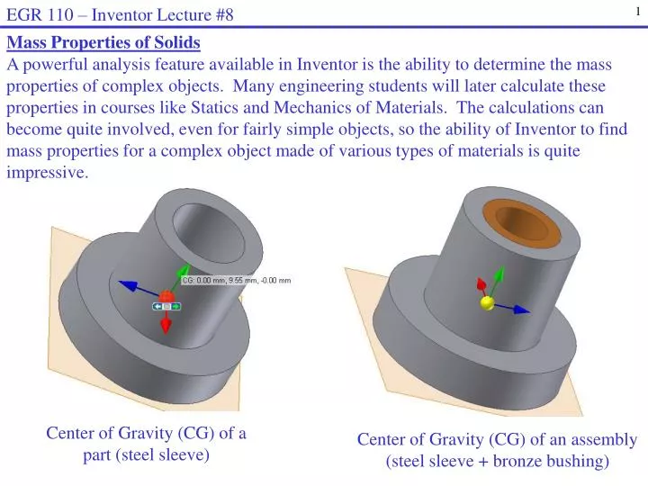
EGR 110 – Inventor Lecture #8 Mass Properties of Solids A powerful analysis feature available in Inventor is the ability to determine the mass properties of complex objects. Many engineering students will later calculate these properties in courses like Statics and Mechanics of Materials. The calculations can become quite involved, even for fairly simple objects, so the ability of Inventor to find mass properties for a complex object made of various types of materials is quite impressive. Center of Gravity (CG) of a part (steel sleeve) Center of Gravity (CG) of an assembly (steel sleeve + bronze bushing)
EGR 110 – Inventor Lecture #8 • Mass Properties of Solids • We can specify the material type for each part, including the density. • Inventor can then calculate: • Volume • Mass • Surface Area • Center of Gravity • Mass Moments of Inertia • Principle Moments of Inertia • Other mass properties • Important notes about finding Center of Gravity with Inventor: • Orientation of axes is critical for each part • Before building each part for an assembly, determine: • Which part will be the base part • Where the origin will be on the base part • What axis orientation will be used on the base part • The origin and axis orientation for an assembly is the same as the origin and axis orientation in the base part.
EGR 110 – Inventor Lecture #8 Example– Selecting the base part, origin, and axis orientation Suppose that the mousetrap below is to be modeled and the center of gravity is to be determined. Before modeling any parts, it is important to: Select the base part (the wooden base is a good choice) Select the origin for the base part (pick a corner perhaps) Select the axis orientation for the base Origin and axis orientation selected Wooden base selected as base part
EGR 110 – Inventor Lecture #8 • Center of Gravity (or center of mass) • It is often important to know the center of gravity or center of mass of a part in order to use it properly. Examples: • The center of gravity of the boom of a crane is important in determining the max load that the crane can lift. • Weights are added to wheels on automobiles in order to “balance” the wheels such that their center of gravity will be in line with the axle of the wheel. • Example – Finding Center of Gravity: Students taking EGR 140 – Statics learn to calculate the center of gravity for various types of objects. Shown on the following slide is a problem from a statics text used recently in EGR 140. The solution is also shown. You do not need to understand the solution at this point, but it will be nice to see that we can build the part in Inventor and achieve the same result.
EGR 110 – Inventor Lecture #8 Problem 5-113 (Statics, 7E, by Beer & Johnston) A bronze bushing is mounted inside a steel sleeve. Knowing that the density of bronze is 8800 kg/m3 and steel is 7860 kg/m3, determine the center of mass of the assembly.
EGR 110 – Inventor Lecture #8 y A B C x z • Analytical Solution(not required for EGR 110, but common in EGR 140): • The coordinates of the “centroid” or center of mass or center of gravity of an object are • referred to as: • Symmetry implies that so we only need to find • Begin by dividing the object into three parts • as shown: • A – Bronze bushing • B – Upper part of steel sleeve • C - Lower part of steel sleeve Note: The terms center of gravity and center of mass are essentially the same. The centroid (center of area or center of volume) is equivalent to the center of gravity only for uniform material (all parts made of the same material).
EGR 110 – Inventor Lecture #8 y A B C x z Analytical Solution (continued): Note that the volume of a cylinder is: and the volume of a hollow cylinder is: So the volumes of parts A, B, and C are as follows (using diameters in meters) :
EGR 110 – Inventor Lecture #8 Analytical Solution (continued): To find the center of mass for the entire object, we will first find the center of mass for each part.
EGR 110 – Inventor Lecture #8 Analytical Solution (continued): If the mass density of each part is known, then the mass can be calculated as follows: m = V or mass = (mass density)(volume) The center of mass of the entire object can now be found by finding the mass and centroid of each part and then by finding a weighted average of the centroids of each part as follows.
EGR 110 – Inventor Lecture #8 • Solution using Inventor • Build a model of Problem 5-113 with Inventor and find the center of gravity. Use the steel sleeve as the base part with the origin at the base of the cylinder and the y-axis along the center of the cylinder. • Create the steel sleeve • Create a new metric part and use a top view (xz) 2D sketch plane since we want the axis of the cylinder along the y-axis • Be sure that the center of the cylinder is located at the origin. • Note that two extrusions are required for the part. Only the sketch plane for the first extrusion is shown below. Centers at origin Steel Sleeve after two extrusions (note the y-axis direction) Sketch Plane (top view) for first extrusion
EGR 110 – Inventor Lecture #8 • Solution using Inventor (continued) • Specify the material and density and check center of gravity • Right-click on the part name (Steel Sleeve) and select iProperties • Select the Physical tab in the iProperties window • Change the material type to Steel, Mild • Note that the density (7.860 g/cm3 or 7860 g/m3) agrees with the value used in the hand analysis • Note that the mass and center of gravity agree with the hand analysis
EGR 110 – Inventor Lecture #8 • Solution using Inventor (continued) • Display the Center of Gravity (CG) icon for the steel sleeve • Select View – Center of Gravity from the main menu. (Select OK if prompted to update the center of gravity.) The center of gravity axes icon should appear. Note that the origin of this icon is located at the CG. • Pause the mouse over the center of gravity icon until the select tool appears. Pick Center of Gravity. • Note that the axes are color coded as follows: Value agrees with hand calculations x-axis: Redy-axis: Greenz-axis: Blue Pause over Center of Gravity icon and select Center of Gravity
EGR 110 – Inventor Lecture #8 • Solution using Inventor (continued) • Create the bronze bushing • Create a new metric part and use a top view (xz) 2D sketch plane • Be sure that the center of the cylinder is located at the origin. • Change the material type to Bronze, Soft Tin • Note that the density (8.874 g/cm3 or 8874 g/m3) agrees with the value used in the hand analysis • Note that the mass and center of gravity agree with the hand analysis
EGR 110 – Inventor Lecture #8 • Solution using Inventor (continued) • Create the assembly • Create a metric assembly drawing. • Use the steel sleeve as the base part. Note that the origin for the assembly will be the same as the origin of the base part. • Next add the bronze bushing to the assembly. • Use an Insert Constraint to complete the assembly. • Note that the mass and center of gravity agree with the hand analysis
EGR 110 – Inventor Lecture #8 • Solution using Inventor (continued) • Copying iProperties to the Clipboard • Select Clipboard from the iProperties window for the assembly. • Paste the iProperties data into NotePad, Word, etc. • Repeat for each part
EGR 110 – Inventor Lecture #8 • Solution using Inventor (continued) • Display the Center of Gravity icon for the assembly • Select View – Center of Gravity from the main menu. (Select OK if prompted to update the center of gravity.) The center of gravity axes icon should appear. • Note that the origin of this icon is located at the CG so viewing the assembly from different directions shows the location of the CG more clearly. • Inventor does not display the coordinates of the CG as it does with parts.
EGR 110 – Inventor Lecture #8 • Adding New Materials • The previous example used two readily available materials (Steel, Mild and Bronze, Soft Tin). We can add other materials if necessary. First view the available materials as follows: • Select Tools – Material – Inventor Material Library • Select ABS Plastic (in order to add a similar material) Note: Inventor shows the density of ABS plastic as 1.060 g/cm3 or as 0.038 lbm/in3. These are equivalent as seen below.
EGR 110 – Inventor Lecture #8 • Adding New Materials (continued) • 3D printers are used in class to build parts using ABS plastic. However, 3D printers include options for either sparse or dense material, so we may wish to create a new material in Inventor with a different density. • Example: A student designs a wheel using Inventor. The student selects ABS Plastic for the material. Checking iProperties reveals the following: • Mass = 0.050 kg • Volume = 47419 mm3 • Density (of ABS Plastic) = 1.060 g/cm3 = 0.038295 lbm/in3 Problem: The student weighs the wheel and its mass is only 28 g (not 50 g). So a new material with the appropriate density will be added to Inventor.
EGR 110 – Inventor Lecture #8 • Adding New Materials (continued) • The density of the new material can be calculated as follows: Since mass varies linearly with density (m = pV), another way to find the new density is scale it using 2 = 1*(m2/m1).
EGR 110 – Inventor Lecture #8 • Adding New Materials (continued) • Now we can add a new material to Inventor with the correct density: • Select Tools – Material – Inventor Material Library • Select ABS Plastic (in order to add a similar material) • Select Create New Material • The new material is a copy of ABS Plastic and is called ABS Plastic (1). Change the name to ABS Plastic – Wheel • Change the Density to 0.021 lbm/in3 • Select Apply to save the changes
EGR 110 – Inventor Lecture #8 • Adding New Materials (continued) • Now select the new material and check the density and mass as follows: • Select iProperties for the wheel • Change the Material to ABS Plastic – Wheel • Select Apply New material New density New mass