TPC sector alignment
This study presents a detailed simulation framework for aligning tracks within inner and outer sectors of a detector under magnetic influence. Utilizing a novel standalone simulator, we analyze the effects of misalignment through a defined misalignment matrix. The study includes results from over 5000 track simulations, revealing insights into the performance under specific magnetic conditions (0.5 T) and particle transformation. Our findings address how rotation and translation of the chambers impact track alignment, providing foundational steps for future calibration and validation strategies.


TPC sector alignment
E N D
Presentation Transcript
TPC sector alignment Marian Ivanov
Outlook • Simulation • Alignment algorithm – Inner outer sectors • Results
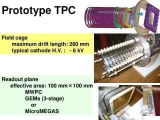
Simulation • Stand alone simulator • Ideal helix • Pt range >0.4 GeV • Exp(-x/0.4) distribution • Magnetic field 0.5 T • Tracks inside of one sector, inner and outer • Pads and pad-rows and time bins inside chamber perfectly aligned • Outer sector misaligned • Characterize by TGeoHMatrix
Motivation • Why to use tracks in the magnetic field for the alignment? • Rotation and translation of the chambers can be affected by the presence of the magnetic field
Simulation • Example results: • Misalignment matrix: • .999999 -0.000873 0.000698 Tx = -0.2 • 0.000873 1.000000 -0.000174 Ty = 0.2 • -0.000698 0.000175 1.000000 Tz = 0.2 • Space charge effect and ExB switched off
Track fitting • AliRieman (new standalone class) used for track fitting • Less than 1 s for track fitting (20000 tracks) • Picture: • Pt resolution for non aligned sectors 1/ptrec-1/pt
Outer sector Inner sector Alignment (0)
Alignment (1) • Separate track –fitting in inner and outer sector • Parabolic track approximation at the middle reference plane in both chambers • Minimization of the chi2 distance between space point in reference plane of upper chamber and corresponding extrapolation of the inner track • TMinuit used
Alignment (2) • FCN=1257.14 FROM MIGRAD STATUS=CONVERGED 132 CALLS 133 TOTAL EDM=2.42528e-12 STRATEGY= 1 ERROR MATRIX UNCERTAINTY 0.0 per cent EXT PARAMETER STEP FIRST NO. NAME VALUE ERROR SIZE DERIVATIVE 1 rx 1.07144e-02 8.90503e-04 1.58139e-05 -2.35997e-01 2 ry 3.95478e-02 1.99467e-03 6.68023e-06 -2.30862e+01 3 rz 4.82396e-02 5.75040e-03 9.11108e-06 1.29964e-01 4 sx -1.96256e-01 4.94420e-03 4.00290e-05 -3.84583e+00 5 sy 2.05511e-01 1.60506e-02 2.49723e-05 7.85195e-02 6 sz 1.99985e-01 5.07757e-03 2.49634e-05 5.15010e+00
Alignment – Covariance matrix • PARAMETER CORRELATION COEFFICIENTS • NO. GLOBAL 1 2 3 4 5 6 1 0.86752 1.000 0.018 -0.192 -0.025 0.266 0.014 2 0.99573 0.018 1.000 0.023 -0.921 -0.021 0.971 3 0.99896 -0.192 0.023 1.000 -0.005 -0.996 0.027 4 0.97508 -0.025 -0.921 -0.005 1.000 0.002 -0.819 5 0.99900 0.266 -0.021 -0.996 0.002 1.000 -0.025 6 0.99065 0.014 0.971 0.027 -0.819 -0.025 1.000
Results (5000 tracks) • Original misalignment matrix - Amis • matrix - tr=1 rot=1 refl=0 0.999999 -0.000873 0.000698 Tx = -0.2 0.000873 1.000000 -0.000174 Ty = 0.2 -0.000698 0.000175 1.000000 Tz = 0.2 • Residual matrix – Afit.Inverse()*Amis • matrix - tr=1 rot=1 refl=0 1.000000 -0.000020 0.000085 Tx = -0.0121112 0.000020 1.000000 0.000016 Ty = -0.00518356 -0.000085 -0.000016 1.000000 Tz = 0.0116462
Results –Rotation Z • Left side – 2000 track samples • Right side – 5000 track samples
Results –Rotation Y • Left side – 2000 track samples • Right side – 5000 track samples
Results –Rotation X • Left side – 2000 track samples • Right side – 5000 track samples
Translation X • Left side – 2000 track samples • Right side – 5000 track samples
Translation Y • Left side – 2000 track samples • Right side – 5000 track samples
Translation Z • Left side – 2000 track samples • Right side – 5000 track samples
Conclusion • Huge statistic needed to develop and validate alignment procedure • First estimation made • How to proceed? • Use and develop stand alone simulator for calibration study? • 5000 tracks *100 samples =500000 tracks • Or use AliRoot framework to generate space points • Apply different systematic shift on the level of space points • Rotation, translation, ExB, space charge (parameterization needed)