Load Cell Signal Amplification for Elevator Safety
110 likes | 201 Views
Learn how to amplify load cell sensor signals for elevator load limiting with the INA126 in single supply mode. Calibration info provided for 1250kg load cells. No need for high accuracy in lower weight range.

Load Cell Signal Amplification for Elevator Safety
E N D
Presentation Transcript
INA126 Load Cell Analysis Tim Green, MGTS Precision Op Amp Applications Manager October 23, 2018
Summary For 5V single supply maximum output and input range is achieved by tying the REF pin to GND. For 5V bridge excitation, differential input and output is summarized below. Use INA-CMV-CALC (link included in follow-on slides) calculator to see linear operating region of instrumentation amplifiers.
Customer Inputs I am working in a new design in which I need to amplify the signal of a load cell sensor on a small elevator. I attach the datasheet of the load cell (I am using the 1250kg model)F.TECNICA SWK (ES·D1067-R00).pdf I do not need too much accuracy in the measurements. It is used just as a load limiter and it is calibrated once installed en each elevator. (first it is calibrated the zero load (which is the weigth of the cabin = 250kg) and after that it is calibrated a known load (around 200kg extra so 450kg in total)) The sensibilty is 1,3...2mV/V and I don not need to have accuracy nor linearity in the zone of 0-150kg. The zone I am interested in have quite good readings is 150-1250kg. I have though in using the INA126 in a single power supply mode (I do not have negative power supply) but I have some doubts about the ref input (pin 5) connection. I have design the following scheme • And I want an output from 0V to 4.5V aprox (that is why I configure a gain of aprox. 450 to have 4.5V from 10mV (=2m/V*5V). • My doubt is how I should connect the ref pin to obtain an output from 0V to aprox 4.5V.
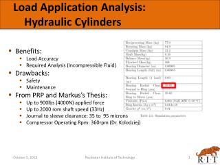
Customer Circuit Transient Analysis Assumptions: Bridge excitation = +5V Common mode input voltage = +2.5V Supplies = +5V, GND Differential input voltage at 5V excitation = 1.2mV to 10mV (assume 10mV for 1250kG, 1.2mV for 150kG) Instrumentation Amplifier Gain = 449.45
Use INA126 http://www.ti.com/tool/ina-cmv-calc
Use INA333 http://www.ti.com/tool/ina-cmv-calc