Fundamentals of Computer Networking: Exploring Internet and Protocols
This presentation offers an introduction to computer networking concepts, Internet structure, protocol layers, services, and network performance. It covers topics such as network edge, physical media, network core, protocol layers, and service models. The content delves into the basics of data transfer mechanisms like circuit switching and packet switching. Additionally, it discusses the roles of end systems, application layers, and the fundamental elements of network communication. Through detailed explanations and examples, learners will gain a foundational understanding of computer networking principles.

Fundamentals of Computer Networking: Exploring Internet and Protocols
E N D
Presentation Transcript
CPE 400 / 600Computer Communication Networks Lecture 3 Chapter 1Introduction slides are modified from J. Kurose & K. Ross Introduction
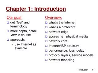
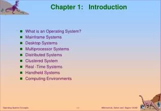
Goal: get “feel” and terminology more depth, detail later in course Overview: what’s the Internet? what’s a protocol? network edge; hosts, access net, physical media network core: packet/circuit switching, Internet structure performance: loss, delay, throughput protocol layers, service models security history Chapter 1: Introduction Introduction
network edge: applications and hosts A closer look at network structure: • access networks, physical media: wired, wireless communication links • network core: • interconnected routers • network of networks Introduction
Services TCP: reliable data transfer S`MTP (email), HTTP (Web), FTP (file transfer), Telnet (remote login) UDP: unreliable data transfer streaming media, teleconferencing, DNS, Internet telephony Physical Media Bit: propagates between transmitter/rcvr pairs physical link: what lies between transmitter & receiver guided media: signals propagate in solid media: copper, fiber, coax unguided media: signals propagate freely, e.g., radio Introduction
end systems (hosts): run application programs e.g. Web, email at “edge of network” peer-peer client/server The network edge: • client/server model • client host requests, receives service from always-on server • e.g. Web browser/server; email client/server • peer-peer model: • minimal (or no) use of dedicated servers • e.g. Skype, BitTorrent Introduction
mesh of interconnected routers the fundamental question: how is data transferred through network? circuit switching: dedicated circuit per call: telephone network packet-switching: data sent thru network in discrete “chunks” The Network Core Introduction
Internet is roughly hierarchical a packet passes through many networks! Tier 3 ISP local ISP local ISP local ISP local ISP local ISP local ISP local ISP local ISP Tier-2 ISP Tier-2 ISP Tier-2 ISP Tier-2 ISP Tier-2 ISP Internet structure: network of networks Tier 1 ISP Tier 1 ISP Tier 1 ISP Introduction
Lecture 3: roadmap 1.4 Performance in packet-switched networks • Delay • loss • throughput 1.5 Protocol layers, service models Chapter 2: Application Layer • Intro Introduction
packets queue in router buffers packet arrival rate to link exceeds output link capacity packets queue, wait for turn packet being transmitted (delay) packets queueing (delay) free (available) buffers: arriving packets dropped (loss) if no free buffers How do loss and delay occur? A B Introduction
1. nodal processing: check bit errors determine output link transmission A propagation B nodal processing queueing Four sources of packet delay • 2. queueing • time waiting at output link for transmission • depends on congestion level of router Introduction
3. Transmission delay: R=link bandwidth (bps) L=packet length (bits) time to send bits into link = L/R 4. Propagation delay: d = length of physical link s = propagation speed in medium (~2x10⁸ m/sec) propagation delay = d/s transmission A propagation B nodal processing queueing Delay in packet-switched networks Note: s and R are very different quantities! Introduction
cars “propagate” at 100 km/hr toll booth takes 12 sec to service car (transmission time) car~bit; caravan ~ packet Q: How long until caravan is lined up before 2nd toll booth? Time to “push” entire caravan through toll booth onto highway = 12*10 = 120 sec Time for last car to propagate from 1st to 2nd toll both: 100km/(100km/hr)= 1 hr A: 62 minutes 100 km 100 km ten-car caravan toll booth toll booth Caravan analogy Introduction
Cars now “propagate” at 1000 km/hr Toll booth now takes 1 min to service a car Q:Will cars arrive to 2nd booth before all cars serviced at 1st booth? Yes! After 7 min, 1st car at 2nd booth and 3 cars still at 1st booth. 1st bit of packet can arrive at 2nd router before packet is fully transmitted at 1st router! See Ethernet applet at AWL Web site 100 km 100 km ten-car caravan toll booth toll booth Caravan analogy (more) Introduction
Nodal delay • dproc = processing delay • typically a few microsecs or less • dqueue = queuing delay • depends on congestion • dtrans = transmission delay • = L/R, significant for low-speed links • dprop = propagation delay • a few microsecs to hundreds of msecs Introduction
R=link bandwidth (bps) L=packet length (bits) a=average packet arrival rate Queueing delay (revisited) traffic intensity = La/R • La/R ~ 0: average queueing delay small • La/R -> 1: delays become large • La/R > 1: more “work” arriving than can be serviced, average delay infinite! Introduction
“Real” Internet delays and routes • What do “real” Internet delay & loss look like? • Traceroute program: provides delay measurement from source to router along end-end Internet path towards destination. For all i: • sends three packets that will reach router i on path towards destination • router i will return packets to sender • sender times interval between transmission and reply. 3 probes 3 probes 3 probes Introduction
“Real” Internet delays and routes traceroute: gaia.cs.umass.edu to www.eurecom.fr Three delay measurements from gaia.cs.umass.edu to cs-gw.cs.umass.edu 1 cs-gw (128.119.240.254) 1 ms 1 ms 2 ms 2 border1-rt-fa5-1-0.gw.umass.edu (128.119.3.145) 1 ms 1 ms 2 ms 3 cht-vbns.gw.umass.edu (128.119.3.130) 6 ms 5 ms 5 ms 4 jn1-at1-0-0-19.wor.vbns.net (204.147.132.129) 16 ms 11 ms 13 ms 5 jn1-so7-0-0-0.wae.vbns.net (204.147.136.136) 21 ms 18 ms 18 ms 6 abilene-vbns.abilene.ucaid.edu (198.32.11.9) 22 ms 18 ms 22 ms 7 nycm-wash.abilene.ucaid.edu (198.32.8.46) 22 ms 22 ms 22 ms 8 62.40.103.253 (62.40.103.253) 104 ms 109 ms 106 ms 9 de2-1.de1.de.geant.net (62.40.96.129) 109 ms 102 ms 104 ms 10 de.fr1.fr.geant.net (62.40.96.50) 113 ms 121 ms 114 ms 11 renater-gw.fr1.fr.geant.net (62.40.103.54) 112 ms 114 ms 112 ms 12 nio-n2.cssi.renater.fr (193.51.206.13) 111 ms 114 ms 116 ms 13 nice.cssi.renater.fr (195.220.98.102) 123 ms 125 ms 124 ms 14 r3t2-nice.cssi.renater.fr (195.220.98.110) 126 ms 126 ms 124 ms 15 eurecom-valbonne.r3t2.ft.net (193.48.50.54) 135 ms 128 ms 133 ms 16 194.214.211.25 (194.214.211.25) 126 ms 128 ms 126 ms 17 * * * 18 * * * 19 fantasia.eurecom.fr (193.55.113.142) 132 ms 128 ms 136ms trans-oceanic link * means no response (probe lost, router not replying) Introduction
Packet loss • queue (aka buffer) preceding link in buffer has finite capacity • packet arriving to full queue dropped (aka lost) • lost packet may be retransmitted by previous node, by source end system, or not at all buffer (waiting area) packet being transmitted A B packet arriving to full bufferis lost Introduction
pipe that can carry fluid at rate Rsbits/sec) pipe that can carry fluid at rate Rcbits/sec) Throughput • throughput: rate (bits/time unit) at which bits transferred between sender/receiver • instantaneous: rate at given point in time • average: rate over longer period of time link capacity Rcbits/sec link capacity Rsbits/sec server, with file of F bits to send to client server sends bits (fluid) into pipe Introduction
Rs > RcWhat is average end-end throughput? Rsbits/sec Rcbits/sec Rcbits/sec bottleneck link link on end-end path that constrains end-end throughput Throughput (more) • Rs < RcWhat is average end-end throughput? Rsbits/sec Introduction
Throughput: Internet scenario • per-connection end-end throughput: min(Rc,Rs,R/10) • in practice: Rc or Rs is often bottleneck Rs Rs Rs R Rc Rc Rc 10 connections (fairly) share backbone bottleneck link Rbits/sec Introduction
Lecture 3: roadmap 1.4 Performance in packet-switched networks • Delay • loss • throughput 1.5 Protocol layers, service models Chapter 2: Application Layer • Intro Introduction
Networks are complex! many “pieces”: hosts routers links of various media applications protocols hardware, software Question: Is there any hope of organizing structure of network? Or at least our discussion of networks? Protocol “Layers” Introduction
ticket (complain) baggage (claim) gates (unload) runway landing airplane routing ticket (purchase) baggage (check) gates (load) runway takeoff airplane routing airplane routing Organization of air travel • a series of steps Introduction
ticket ticket (purchase) baggage (check) gates (load) runway (takeoff) airplane routing ticket (complain) baggage (claim gates (unload) runway (land) airplane routing baggage gate airplane routing airplane routing takeoff/landing airplane routing departure airport intermediate air-traffic control centers arrival airport Layering of airline functionality Layers: each layer implements a service • via its own internal-layer actions • relying on services provided by layer below Introduction
Why layering? Dealing with complex systems: • explicit structure allows identification, relationship of complex system’s pieces • layered reference model for discussion • modularization eases maintenance, updating of system • change of implementation of layer’s service transparent to rest of system • e.g., change in gate procedure doesn’t affect rest of system • layering considered harmful? Introduction
application: supporting network applications FTP, SMTP, HTTP transport: process-process data transfer TCP, UDP network: routing of datagrams from source to destination IP, routing protocols link: data transfer between neighboring network elements PPP, Ethernet physical: bits “on the wire” application transport network link physical Internet protocol stack Introduction
presentation: allow applications to interpret meaning of data, e.g., encryption, compression, machine-specific conventions session: synchronization, checkpointing, recovery of data exchange Internet stack “missing” these layers! these services, if needed, must be implemented in application needed? application presentation session transport network link physical ISO/OSI reference model Introduction
network link physical link physical M M M Ht M Hn Hn Hn Hn Ht Ht Ht Ht M M M M Ht Ht Hn Hl Hl Hl Hn Hn Hn Ht Ht Ht M M M source Encapsulation message application transport network link physical segment datagram frame switch destination application transport network link physical router Introduction
Covered a “ton” of material! Internet overview what’s a protocol? network edge, core, access network packet-switching vs circuit-switching Internet structure performance: loss, delay, throughput layering, service models You now have: context, overview, “feel” of networking more depth, detail to follow! Lecture 3: Summary Introduction
Lecture 3: roadmap 1.4 Performance in packet-switched networks • Delay • loss • throughput 1.5 Protocol layers, service models Chapter 2: Application Layer • Intro Introduction
2.1 Principles of network applications 2.2 Web and HTTP 2.3 FTP 2.4 Electronic Mail SMTP, POP3, IMAP 2.5 DNS 2.6 P2P applications 2.7 Socket programming with TCP 2.8 Socket programming with UDP Chapter 2: Application layer 2: Application Layer
Goals: conceptual, implementation aspects of network application protocols transport-layer service models client-server paradigm peer-to-peer paradigm learn about protocols by examining popular application-level protocols HTTP, FTP, SMTP / POP3 / IMAP, DNS programming network applications socket API Chapter 2: Application Layer 2: Application Layer
e-mail web instant messaging remote login P2P file sharing multi-user network games streaming stored video clips voice over IP real-time video conferencing grid computing Some network apps 2: Application Layer
write programs that run on (different) end systems communicate over network e.g., web server software communicates with browser software No need to write software for network-core devices Network-core devices do not run user applications applications on end systems allows for rapid app development, propagation application transport network data link physical application transport network data link physical application transport network data link physical Creating a network app 2: Application Layer
Application architectures • Client-server • Peer-to-peer (P2P) • Hybrid of client-server and P2P 2: Application Layer
client/server Client-server architecture server: • always-on host • permanent IP address • server farms for scaling clients: • communicate with server • may be intermittently connected • may have dynamic IP addresses • do not communicate directly with each other 2: Application Layer
peer-peer Pure P2P architecture • no always-on server • arbitrary end systems directly communicate • peers are intermittently connected and change IP addresses Highly scalable but difficult to manage 2: Application Layer
Hybrid of client-server and P2P Skype • voice-over-IP P2P application • centralized server: finding address of remote party: • client-client connection: direct (not through server) Instant messaging • chatting between two users is P2P • centralized service: client presence detection/location • user registers its IP address with central server when it comes online • user contacts central server to find IP addresses of buddies 2: Application Layer
Process: program running within a host. within same host, two processes communicate using inter-process communication (defined by OS). processes in different hosts communicate by exchanging messages Client process: process that initiates communication Server process: process that waits to be contacted Note: applications with P2P architectures have client processes & server processes Processes communicating 2: Application Layer