Download
1 / 13
150 likes | 202 Views
Learn about pneumatic components like solenoid valves, regulators, and cylinders from this guide. Discover how to build a working pneumatic circuit and understand energy transformation and storage in pneumatic systems. Test your knowledge by determining performance characteristics after building and testing the circuit.

E N D
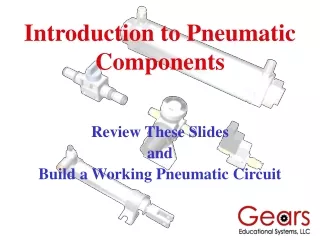
Introduction to Pneumatic Components Review These Slides and Build a Working Pneumatic Circuit
Introduction to Pneumatic Components Bicycle Pump Energy Transformation Solenoid Valve Energy Control Storage Reservoir Energy Storage Pneumatic Cylinder or Linear Actuator Energy Transformation 3 Way Shut Off Valve Energy Control Order of Air Flow Regulator Energy Control
Bicycle Pump Piston Rod Charges the Pneumatic Battery Pump Handle Pump Tube or Cylinder Converts Mechanical Energy into the Potential Energy of Pressurized Air Pressure Gauge Fill Valve With Locking Lever Piston Foot Stand
Pneumatic Reservoir Energy Stored as Compressed Air One Touch Quick Connect Fitting Connects to 3 Way Valve Schrader Valve Connects to Pump Air Storage Capacity is a Function of Pressure x Volume = Capacity Mounting Nuts (2)
3 Way Valve Finger Knob Shown in Off Position Inlet Port From Reservoir Outlet Port To Regulator Direction Arrow On Valve Body Three Operational States or Modes OFF – Vent – On
The Regulator Controlled Pressure Side Pressure Gauge 0-150 psi 0-1 MPa Pressure Adjusting Knob *Pull out before turning *Push in to lock *Turn Clockwise to Raise Pressure. Air Flow Directional Arrow High Pressure Inlet Lower Pressure Settings Means Less Air Consumption
The Regulator continued Note: Be certain to verify the direction of air flow through the regulator. The incoming air (from The 3 Way Valve) Enters the port marked with an arrow.
3/2 Solenoid Valve Valve Body Actuator Port “A2” Pressure Port “P1” From Regulator Exhaust Port “E” Solenoid Wires
The Pneumatic Cylinder or Linear Actuator Speed Valve Piston and Rod Clevis One Touch Quick Connect Fitting Cylinder Body Pneumatic Mounting Bracket Cylinder Force = Pressure x Piston Area
Pneumatic Component Connections Build It Test It Use It
After Building and Testing the Pneumatic Circuit Determine These Performance Characteristics • How many times will the pneumatic cylinder cycle at 50 psi when the reservoir is charged to 150 psi? • What is the theoretical force of the piston at 50 psi? • What is the actual force of the piston at 50 psi? • What is the speed of the piston in inches per second at 50 psi? • Does pressure affect speed and if so, can you measure and graph the relationship? Which answers can be found mathematically? Which should be measured directly?