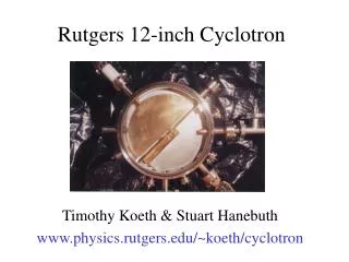
Recirculation Concept - Cyclotron
Recirculation Concept - Cyclotron. Radio frequency alternating voltage. D-shaped RF cavities. time t =0. Lawrence: 4” – 80 keV 11” - 1.2 MeV. Hollow metal drift tubes. time t =½ RF period. Orbit radius increases with momentum Orbital Frequency independent of momentum

Recirculation Concept - Cyclotron
E N D
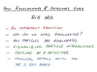
Presentation Transcript
Recirculation Concept - Cyclotron Radio frequency alternating voltage D-shaped RF cavities time t =0 Lawrence: 4” – 80 keV 11” - 1.2 MeV Hollow metal drift tubes time t =½ RF period • Orbit radius increases with momentum • Orbital Frequency independent of momentum • Particle motion and RF in phase
Equilibrium Orbit Magnetic Force Centrifugal Force = Constant revolution frequency momentum radius magnetic field
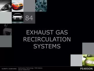
Synchrotron Ring Schematic Bending magnets Accelerating Voltage • During acceleration, momentum increases • Increase magnetic field during acceleration. • Constant orbital radius Vacuum tube Focusing magnets
Equilibrium Orbit momentum Constant revolution frequency radius magnetic field
CERN Seen from the Air • Tunnels of CERN accelerator complex superimposed on a map of Geneva. • Accelerator is 50 m underground • 25 km in circumference
Alors, c’est fini! Et maintenant?
Interaction of Charged Particles with Matter All particle detectors ultimately use interaction of electric charge with matter Track Chambers Calorimeters Even Neutral particle detectors Ionization Multiple Scattering Cerenkov Transition Radiation Electron’s small mass - radiation
You could actually see what was going on 1960s computer
Bubble Chamber – ionization trails in superheated liquid hydrogen Electron knocked out of atom Spirals in magnetic field
Generic Detector • Layers of Detector Systems around Collision Point R.S. Orr 2009 TRIUMF Summer Institute
Generic Detector • Different Particles detected by different techniques. • Tracks of Ionization – Tracking Detectors • Showers of Secondary particles – Calorimeters R.S. Orr 2009 TRIUMF Summer Institute
Generic Detector • Different Particles detected by different techniques. • Tracks of Ionization – Tracking Detectors • Showers of Secondary particles – Calorimeters R.S. Orr 2009 TRIUMF Summer Institute
Computer Display of Event • Layers of Detector Systems around Collision Point R.S. Orr 2009 TRIUMF Summer Institute
ATLAS Detector • Different Particles detected by different techniques. • Tracks of Ionization – Tracking Detectors • Showers of Secondary particles – Calorimeters R.S. Orr 2009 TRIUMF Summer Institute
ATLAS Wedge • Different Particles detected by different techniques. • Tracks of Ionization – Tracking Detectors • Showers of Secondary particles – Calorimeters R.S. Orr 2009 TRIUMF Summer Institute
Wire Chamber R.S. Orr 2009 TRIUMF Summer Institute
3 stages in signal generation 1) Ionization by track passing through cell 2) Ionization drifts in E field time • 3) In high E field region near wire, primary ionization electrons gain enough energy to start ionizing the gas • Avalanche • More charges • Charge amplification • Noise free amplifier microvolt signal if no amplification R.S. Orr 2009 TRIUMF Summer Institute
Generic Detector R.S. Orr 2009 TRIUMF Summer Institute
Generic Detector R.S. Orr 2009 TRIUMF Summer Institute
Simple Drift Chamber R.S. Orr 2009 TRIUMF Summer Institute
TRT endcap A+B TRT barrel Pixels TRT endcap C SCT endcap SCT barrel The ATLAS Inner Detector
ATLAS Tracker R.S. Orr 2009 TRIUMF Summer Institute
Inner Detector (ID) • The Inner Detector (ID) comprises four sub-systems: • Pixels (0.8 108 channels) • Silicon Tracker (SCT) • (6 106 channels) • Transition Radiation Tracker (TRT) • (4 105 channels
ATLAS Wedge • Different Particles detected by different techniques. • Tracks of Ionization – Tracking Detectors • Showers of Secondary particles – Calorimeters R.S. Orr 2009 TRIUMF Summer Institute
PN Junction R.S. Orr 2009 TRIUMF Summer Institute
Pixel Layer-2 – half shell Pixel Layer2, once clamped, outside “Ready for installation” date is 1st April 2007 Pixel Layer2, once clamped, inside
ATLAS Wedge • Different Particles detected by different techniques. • Tracks of Ionization – Tracking Detectors • Showers of Secondary particles – Calorimeters R.S. Orr 2009 TRIUMF Summer Institute
Why Is It Called a Calorimeter? Charged Particle Electrical Signal Proportional to Incoming Energy Liquid Argon/Metal Kinetic Energy of Particle Converted to Ionization Of Liquid Argon Readout Electronics
Comparison of Hadronic & Electromagnetic Showers R.S. Orr 2009 TRIUMF Summer Institute
LAr and Tile Calorimeters Tile barrel Tile extended barrel LAr hadronic end-cap (HEC) LAr EM end-cap (EMEC) LAr EM barrel LAr forward calorimeter (FCAL)