Diffraction Model for Diffraction
Diffraction Model for Diffraction. (1). Tom Cuypers 1,2 Se Baek Oh 3 Tom Haber 1 Philippe Bekaert 1 Ramesh Raskar 3. (2). (3). Represent light as particles travelling in straight lines Simple mathematics Realistic rendering of light phenomena Efficient. Geometric Optics. Wave Phenomena.


Diffraction Model for Diffraction
E N D
Presentation Transcript
Diffraction Model for Diffraction (1) Tom Cuypers1,2Se Baek Oh3Tom Haber1Philippe Bekaert1Ramesh Raskar3 (2) (3)
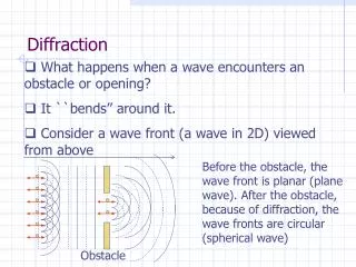
Represent light as particles travelling in straight lines Simple mathematics Realistic rendering of light phenomena Efficient Geometric Optics
Goal Wave BSDF
Related Work • Phase Tracking • Make changes tocurrent software • Slow Moravec – 3D Graphics and the Wave Theory (Siggraph 1981) Ziegler et al. - Lighting and Occlusion in a Wave-Based Framework (Eurographics 2008)
Related Work • Phase Tracking • Diffractionshaders • Assumptionsaboutlocationobserverand light Stam – Diffraction Shaders (Siggraph 1999) Rendering Iridescent Colors of Optical Disks - Sun et a (Siggraph 2006)
Related Work • Phase Tracking • Diffractionshaders • Edgediffraction • Make changes tocurrentsoftware Nicolas Tsingos, Thomas Funkhouser, Addy Nganand Ingrid Carlbom– Modeling Acoustics in Virtual Environments Using the Uniform Theory of Diffraction. (Siggraph 2001)
Wigner Distribution Function • Fourieroptics light representation • Simulatingdiffractionandinterference • Relationshipwithgeometricoptics ’
Spatial Frequency θ λ } 1 u
Wigner Distribution Function • Simulate parallel waves as rays • Propagation of light u z = 0 Zhang and Levoy – Wigner Distribution and How They Relate to the Light Field – ICCP 2009 Oh et al. – Rendering Wave Effects with Augmented Light Fields - Eurographics 2010 x
Wigner Distribution Function • Simulate parallel waves as rays • Propagation of light • Projection Zhang and Levoy – Wigner Distribution and How They Relate to the Light Field – ICCP 2009 Oh et al. – Rendering Wave Effects with Augmented Light Fields - Eurographics 2010
Interaction u u Assumption 2 Microsurfaceinfinitlythin Assumption 1 Coherent Light (laser) x x
Propagation u u I x x x I x
Calculating WDF • Description of the microsurface: t(x) • Amplitude[ t(x) ]: amount of light transmittedon x • Phase[t(x) ]: delay of light on x (duetorefraction index) • Orientation of the incomingplanewave () 2A
Rendering Equation Reflected Light Description of the microstructure t(x) : ) Wave BSDF
Wave BSDF Θ Θ x x
Statistical Wave BSDF • Microsurfacenotalwaysknown • Describemicrosurface as • Heightfunction h(x) • Variance 0 100 200
Limitations • Paraxialregion: more accurate closer to the normal • Surfacesinfinitelythin • No interreflections
Benefits Works in near- and far-field
Benefits Works in near- and far-field
Benefits Minimal changes torendering software PhysicallyBased Ray Tracing (PBRT)
Benefits Minimalcode function W = wigner(Ex) N = length(Ex); x = ifftshift(((0:N-1)'-N/2)*2*pi/(N-1)); X = (0:N-1)-N/2; EX1 = ifft( (fft(Ex)*ones(1,N)).*exp( i*x*X/2 )); EX2 = ifft( (fft(Ex)*ones(1,N)).*exp( -i*x*X/2 )); W = (fftshift(fft(fftshift(EX1.*conj(EX2), 2), [], 2), 2));
Benefits Importance sampling efficientrendering
Benefits • Wigner Distribution Function • Non negative results • Coherent and partially coherent light
Future Research • Wigner distribution extensions • Non-linear materials • Thick materials • Non-paraxial region • Polarization • Sound rendering • Inverse problem – scanning
Conclusion • Simulating wave effects using geometric optics • Constructed the Wave BSDF • Minimal changes to current render software • Valid in near- and far-field • Efficient rendering