Analysis of Viewing Direction Post-Transformation in Coordinate Systems
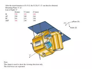
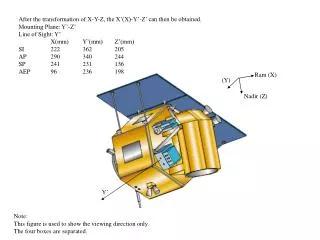
This document illustrates the transformation of coordinates X-Y-Z to X’(X)-Y’-Z’. It includes details about the mounting plane specified by Y’-Z’, along with the line of sight characteristics Y’.X in millimeters, capturing their respective dimensions: Y’(mm), Z’(mm). The provided figure demonstrates the viewing direction solely and emphasizes the separation of the four boxes. The transformation and viewing analyses pave the way for understanding coordinate adjustments in various applications.

Analysis of Viewing Direction Post-Transformation in Coordinate Systems
E N D
Presentation Transcript
Ram (X) Nadir (Z) After the transformation of X-Y-Z, the X’(X)-Y’-Z’ can then be obtained. Mounting Plane: Y’-Z’ Line of Sight: Y’ X(mm) Y’(mm) Z’(mm) SI 222 362 205 AP 290 340 244 SP 241 231 136 AEP 96 236 198 (Y) Y’ Note: This figure is used to show the viewing direction only. The four boxes are separated.